HEIDENHAIN PWM 20 User Manual
Page 140
November 2014
Software description
141
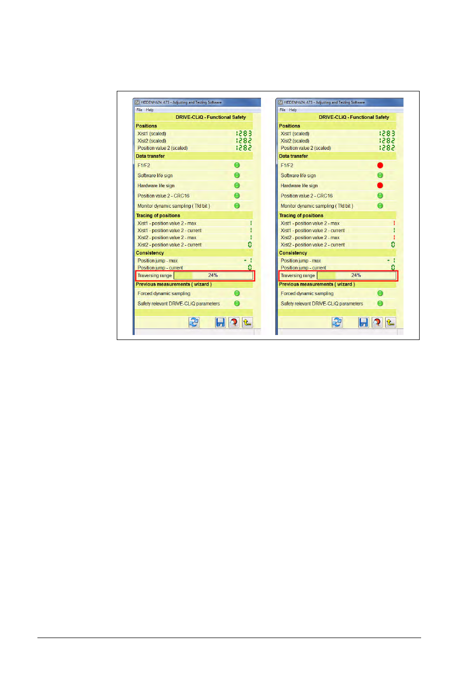
Evaluation of the test for consistency:
Display in green (numerical value and LED symbol) = pass
Display in red (numerical value and LED symbol) = fail
Positions XIST1 (scaled), XIST2 (scaled), position value 2 (scaled):
The display values are converted according to the resolution required for the inspection (safety-
relevant resolution).
Data monitoring:
F1 / F2
Position error bits (encoder-internal)
Software life sign
Life sign generated by the encoder software
Hardware life sign
Life sign generated by the encoder hardware
Position value 2 CRC16
The position 2 created by the scanning ASIC of the encoder is verified by means of an
additional CRC in the encoder.
Monitor dynamic sampling (Tfd bit)
Monitoring bit (Tfd = "test failed") indicating that provoking at least one error during the
dynamic sampling test has failed.
Tracing of positions:
Xist1 - position value 1
Comparison of incremental position and redundant absolute position
Xist2 - position value 2
Comparison of absolute position and redundant absolute position
Max or current
Display of the maximum value or the current value
Consistency:
The consistency of the positions is monitored. The maximum permissible jump on position is "1".
The maximum and the current values are displayed.