Reference mark signal, Connecting cables, Signal diagram: incremental signals11 µapp – HEIDENHAIN PWM 20 User Manual
Page 209
Advertising
210
HEIDENHAIN ATS Software User's Manual
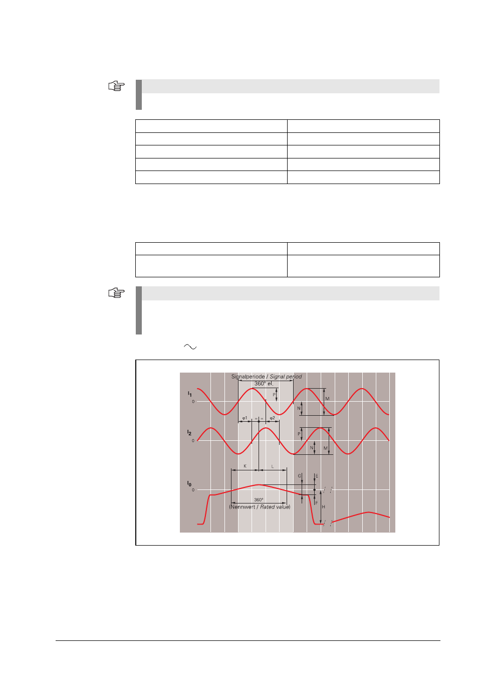
Reference mark
signal
One or several signal peaks I
0
Connecting cables
Signal diagram: Incremental signals
11 µApp
Note
Output signals
Usable component G*
2 to 8.5 µA
Quiescent value H
approx. 14 µA
Quiescent value hidden
approx. 25 µA
Signal-to-noise ratio E, F
min. 0.4 µA
Zero crossovers K, L
180°
90° el.
* Old LS series
LS 50x; LS 80x (e. g. LS 503, LS 803)
Ie0 4 ... 15 µA
Shielded HEIDENHAIN cable
PUR [3(2 x 0.14 mm
2
) + (2 x 1 mm
2
)]
Cable length
Max. 30 m with 90 pF/m distributed
capacitance
Note
The ATS software does not support the high signal levels of the older series of linear
encoders LS 50x (z.B. LS 503) and LS 80x (e.g. LS 803). These signal levels can be inspected
with the PWM 9 test unit.
Advertising