HEIDENHAIN PWM 20 User Manual
Page 191
194
HEIDENHAIN ATS Software User's Manual
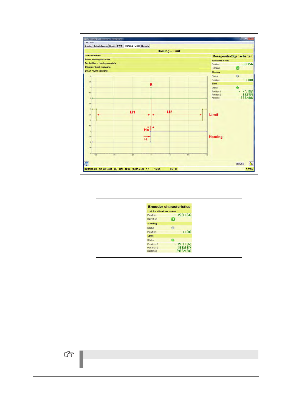
Description of the encoder properties
Position:
Current position of the scanning head
Direction: Traverse direction of the scanning head (right/left) starting at the reference mark
R
Homing
Status:
Green LED
= Homing high level
Gray LED
= Homing low level
Position:
The value corresponds to the distance [mm] of the switching point to the reference
mark. The switching point is referred to as homing point
Ho
. The
H
switching point
is the "switch for the homing track. For tolerances of switching point hysteresis see
mounting instructions of the encoder.
Limit
Status:
Green LED
= Limit high level
Gray LED
= Limit low level
Position 1:
LI1
Distance of limit 1 to reference mark R [mm]
Position 2:
LI2
Distance of limit 2 to reference mark R [mm]
Distance: Sum of limit 1 plus limit 2 (value without sign)
Note
The abbreviations in red color were taken from the mounting instructions (e.g. LIF 48).