4 battery current sensor – SMA SI 4548-US User Manual
Page 54
6 Electrical Connection
SMA America, LLC
54
SI4548-6048-US-BE-en-20
Operating Manual
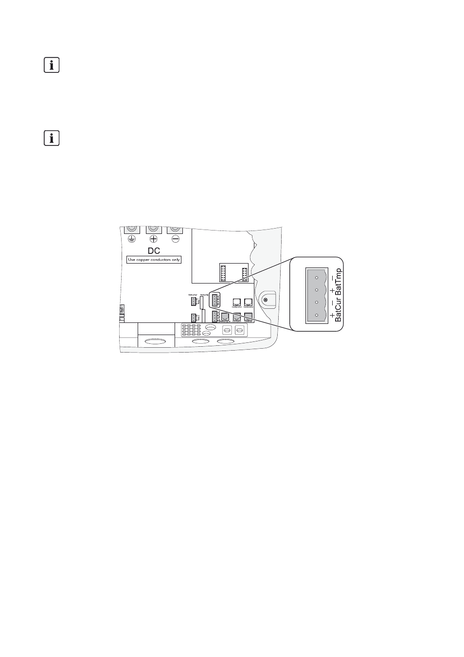
Connecting the Battery Temperature Sensor
1. Pierce a hole at a suitable location in the cable support sleeve using a sharp object.
2. Starting from the outside, lead the insulated conductors with bootlace ferrules through the hole
in the Sunny Island.
3. Connect the insulated conductors correspondingly to the "BatVtgOut" terminal of the four-pole
terminal included in the delivery.
4. Tighten the terminals (torque: 5 in-lb to 7 in-lb (0.56 Nm to 0.79 Nm)).
5. Insert the 4-pole terminal into the "BatTmp" pin connector on the Sunny Island.
6. Attach the battery temperature sensor to the outside of one of the battery cells. Choose a spot
between two cells and in the central area of the battery storage system. The heat generation
during operation is the greatest there.
6.4.4 Battery Current Sensor
In addition to the internal measurement, the Sunny Island provides the possibility to measure the
battery current via a shunt. You need this function if you intend to operate additional DC generators
and DC loads in your off-grid system. Only one battery current sensor is necessary in a cluster; this is
to be connected to the cluster master.
Battery temperature sensor in a cluster
A battery temperature sensor is provided with each Sunny Island. Only one battery temperature
sensor is required for a cluster. Connect the temperature sensor to the master of the cluster.
Polarity of the conductors
The polarity of the two conductors is irrelevant for the functioning of the battery temperature
sensor.