8 digin digital input – SMA SI 4548-US User Manual
Page 61
SMA America, LLC
6 Electrical Connection
Operating Manual
SI4548-6048-US-BE-en-20
61
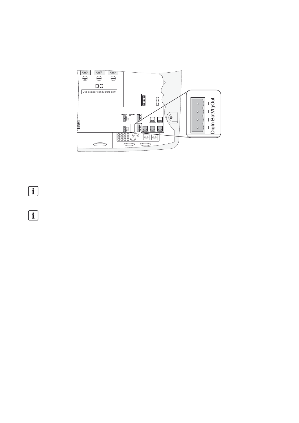
3. Connect the insulated conductors to the "BatVtgOut" terminal of the 4-pole terminal.
4. Tighten the screws of the terminal (torque: 5 in-lb to 7 in-lb (0.56 Nm to 0.79 Nm)).
☑ The BatVtgOut voltage supply is connected.
6.4.8 DigIn Digital Input
The DigIn connection is used as a digital input for external electrical sources.
Connecting the DigIn Digital Input
1. Pierce a hole at a suitable location in the cable support sleeve using a sharp object.
2. Starting from the outside, lead the insulated conductors with bootlace ferrules through the hole
in the Sunny Island.
3. Connect the insulated conductors correspondingly to the "DigIn" terminal of the 4-pole terminal.
4. Tighten the screws of the terminal (torque: 5 in-lb to 7 in-lb (0.56 Nm to 0.79 Nm)).
☑ The DigIn digital input is connected.
Area of the input voltage at the DigIn input
A voltage of between 5 V and 63 V may be present at the digital input DigIn.
Corresponding functions
If you operate the system in mixed operation with generator and utility grid (GenGrid) in
parallel, use the relays on the master device in order to activate the corresponding functions.