SMA SI 4548-US User Manual
Page 59
SMA America, LLC
6 Electrical Connection
Operating Manual
SI4548-6048-US-BE-en-20
59
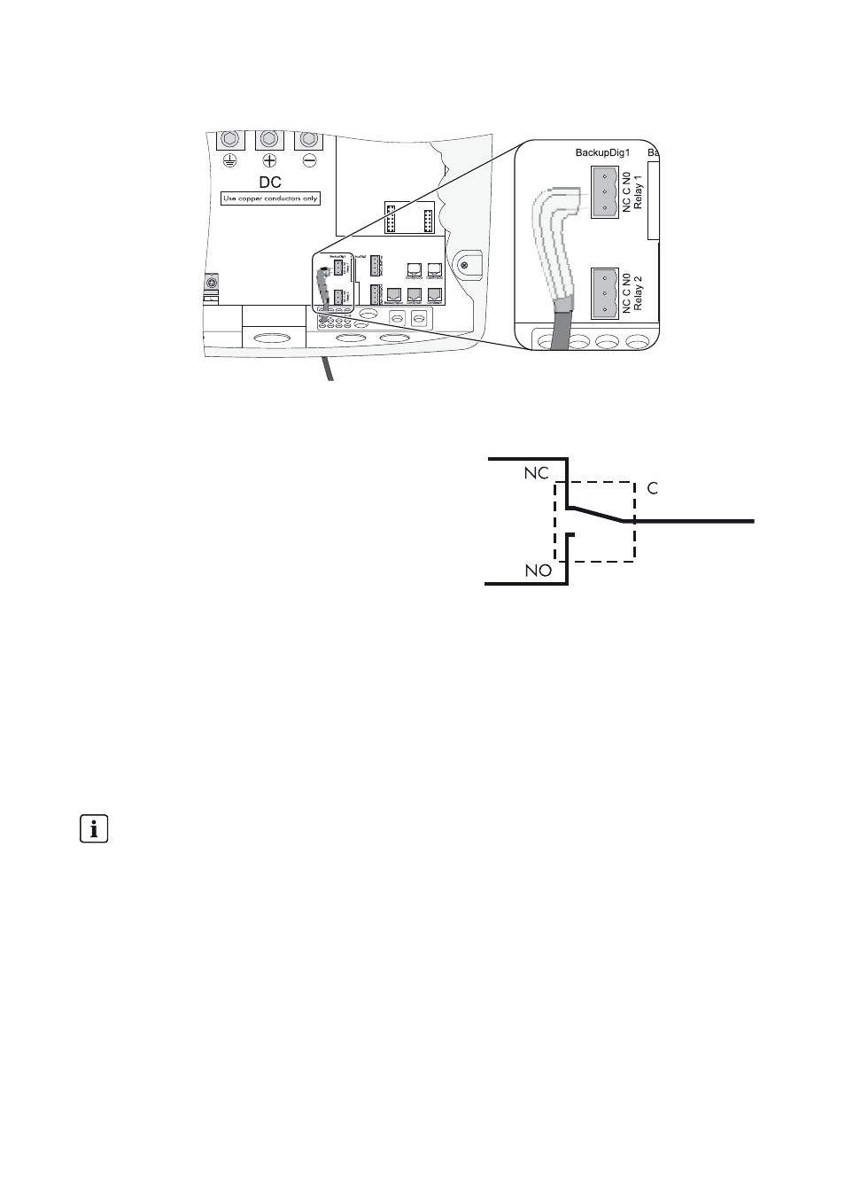
4. Connect the insulated conductors to the supplied three-pole terminal. The pins have the
following meaning:
– NC: normally closed (when the Sunny Island is
off, the relay is closed)
– C: Contact (front contact)
– NO: normally opened (when the Sunny Island
is off, the relay is open)
5. Tighten the terminals (torque: 5 in-lb to 7 in-lb
(0.56 Nm to 0.79 Nm)).
6. Insert the three-pole terminal into corresponding pin connector on the Sunny Island.
Power Contactor for Load Shedding
The Sunny Island can automatically disconnect loads to protect the battery from deep discharge. An
external (AC or DC) power contactor must be installed between the Sunny Island and the loads (see
Section 12.1 "Load Shedding", page 102).
Installing the power supply of a DC power contactor for load shedding (e.g. relay2):
1. Connect the A1 coil terminal of the power contactor to the terminal NO (Relay2).
2. Wire terminal C (Relay2) to the terminal "BatVtgOut +".
3. Wire the A2 coil connector of the power contactor to the terminal "BatVtgOut –".
☑ The control circuit of the power contactor is installed.
Power supply of the DC power contactor
A voltage of 48 V supplied by the battery is present in the control circuit.
• Load the BatVtgOut terminals with a maximum of 0.75 A.