3 minimum clearances, Minimum clearances, Minimum clearance for 1 inverter – SMA SC 500HE-20 Installation User Manual
Page 23
SMA Solar Technology AG
6 Preparation for Installation
Installation Manual
SCxxxHE-20-IA-IEN111210
23
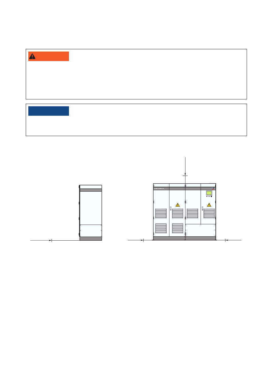
6.1.3 Minimum Clearances
Minimum clearance for 1 inverter
Figure 7: Minimum clearances of the inverter
The exhaust air vent is located at the rear of the inverter.
For the optimum operation of the inverter, observe the following points:
• Do not block or close the exhaust air vent.
• Ensure that the station is equipped with a suitable exhaust air vent.
• In order to prevent thermal short circuits in the inverter, ensure that there are exhaust air ducts
in closed rooms.
• The exhaust air vents must be accessible for cleaning at all times.
8"3/*/(
Danger of fire due to overheating of cables.
Differing cable lengths result in excessive heating of the cables.
• All line conductors from the inverter to the transformer must be of the same length.
• The cable length between the connection points must not exceed a maximum of 15 m.
/05*$&
Damage to the inverter and transformer due to discharged air being sucked in.
• Install the plant so that the inverter cannot suck in any exhaust air.
HE
300 mm
220 mm
300 mm
1 200 mm