2 connection list tab page, 1 ) details of the connection list tab page – Yaskawa JAPMC-CM2304-E User Manual
Page 52
4.2 EtherNet/IP Transmission Definition
4.2.2 Connection List Tab Page
4-6
4.2.2 Connection List Tab Page
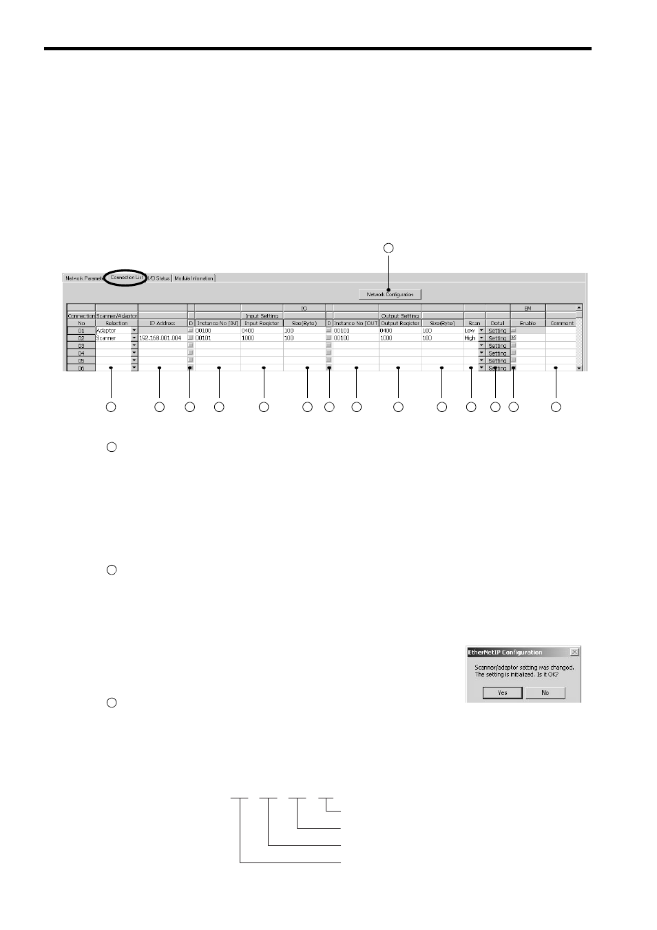
( 1 ) Details of the Connection List Tab Page
Make a list of devices connected to the EtherNet/IP on the Connection List tab page.
The IP address of the device that is assigned to the list as a scanner must be identical to the IP address actually set
for that device. Before assigning a scanner to the list, get the IP address of that device or confirm the IP address of
that device by opening the Network Configuration Search window (refer to page 4-11) while the device is con-
nected to the EtherNet/IP.
After changing the setting on the Connection List tab page, save the definition data by selecting File - Save to
Flash from the Main Menu.
The following shows the details of the items.
Network Configuration Button
Valid only in Online Mode.
When the button is clicked, the Network Configuration Search window that shows what devices are connected
to the EtherNet/IP opens.
Selecting Edit - Network Configuration from the Main Menu will also open the Network Configuration
Search window.
For details of the Network Configuration Search window, refer to 4.2.4 NetWork Configuration Search Win-
dow on page 4-11.
Scanner/Adaptor Selection
Select the adaptor or scanner for the devices to be assigned to the list.
Select Adaptor when the local station is used as a adaptor for other stations. Setting at multiple stations is possi-
ble.
Select Scanner when setting the remote station of I/O communication. Setting at multiple stations is possible.
If the setting is changed after setting Scanner or Adaptor, the message
box shown to the right will be displayed. Clicking the Yes button will
delete the contents that have been assigned to the Connection No.
whose setting has been changed.
IP Address
Enter the IP address of the remote station for which the Scanner is selected.
If the Adaptor is selected, the IP address cannot be entered.
The data input range for the IP address varies in accordance with the field used as shown here.
1
2
3
4
5
6
7
8
9
10
11
12
13
14
15
1
2
3
192.
168.
100.
Field No. 4: 1 to 254
Field No. 3: 0 to 255
Field No. 2: 0 to 255
Field No. 1: 0 to 255 (excluding 127)
Setting example
200