Yaskawa JAPMC-CM2304-E User Manual
Page 69
5.2 Message Send Function
5.2.3 Inputs and Outputs for the Message Send Function
5-7
5
Explicit Message and Explicit Message Send Function
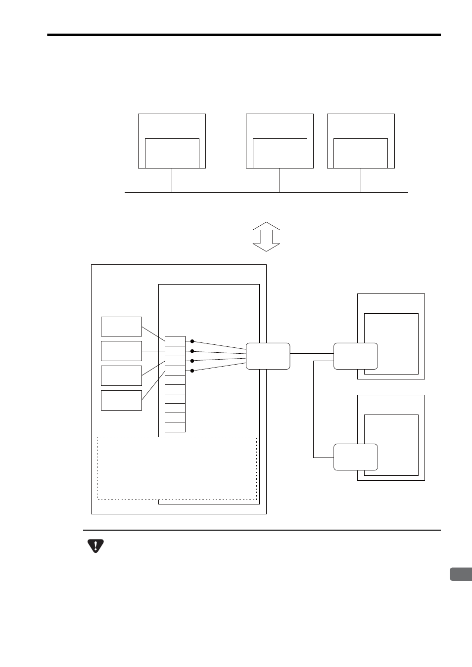
Conceptual Diagram of Transmission Buffer Channels
The following is a conceptual diagram of the transmission buffer channels.
Even if different transmission buffer channels are used, it is not possible to start the MSG-SND functions
simultaneously for one device (IP address). If this is attempted, an error occurs when the MSG-SND function
is executed.
MP2000 Series
Machine Controller
EtherNet/IP
Local IP Address
192.168.1.x
Remote device #1
Remote device #2
Network Configuration Diagram
263IF-01
Local IP Address
192.168.1.x
1
2
4
5
6
7
8
9
10
Transmission
buffer channel
MP2000-series
Machine Controller
MSG-SND
function
MSG-SND
function
MSG-SND
function
3
MSG-SND
function
EtherNet/IP
The MSG-SND functions use the 263IF-01 transmission
buffer channels to perform message communication.
A transmission buffer channel can start only one
MSG-SND function. In other words, one transmission
buffer channel cannot be used to start several
MSG-SND functions simultaneously.
EtherNet/IP
EtherNet/IP
Remote IP Address
192.168.1.y
Remote device #1
EtherNet/IP
port
EtherNet/IP
port
Remote device #2
EtherNet/IP
Remote IP Address
192.168.1.z
EtherNet/IP
port
EtherNet/IP
Remote IP Address
192.168.1.y
EtherNet/IP
Remote IP Address
192.168.1.z