Installation and wiring, Verify drive operation, Prepare the v7 drive – Yaskawa CM013 V7 DeviceNet Option User Manual
Page 9: Installation and wiring -4
Installation 1-4
Installation and Wiring
Verify Drive Operation
Connect power to the drive and verify that the drive functions properly. This includes running the drive from the operator keypad. Refer to
the V7 and V74X Drives Technical Manual, TM.V7.01, for information on connecting and operating the drive.
Prepare the V7 Drive
1.
Remove power from the drive and wait for the charge lamp to be
completely extinguished. Wait at least five additional minutes for the
drive to be completely discharged. Measure the DC bus voltage and
verify that it is at a safe level.
2.
Remove the operator and terminal cover retaining screw.
3.
Remove the operator keypad.
4.
Remove the terminal cover by lifting out the cover.
5.
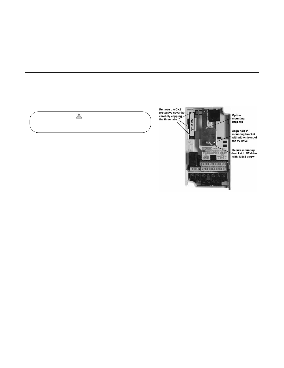
Remove the CN2 cover from the V7 drive housing. Carefully snip the
3 tabs connecting the CN2 cover to the V7 housing and remove the
cover.
6.
Attach the mounting bracket. Align the mounting bracket as shown in
the figure to the right. Secure the mounting bracket to the V7 drive
housing using the M3x8 screw provided.
7.
Wire the V7 drive I/O, power and motor terminals prior to mounting
the V7 DeviceNet Option, as the option will obscure the terminals
when mounted.
Fig 1.2 – Prepare the V7 Drive
Dangerous voltages in excess of 400VDC (230V drives) or 800VDC
(460V drives) are present at the DC bus terminals of the drive.
WARNING!