Connect the drive to the devicenet network, Table 5: devicenet terminal block connections, Set baud rate and node address – Yaskawa DeviceNet Option Card CM059 User Manual
Page 15
15
Connect The Drive To The DeviceNet Network
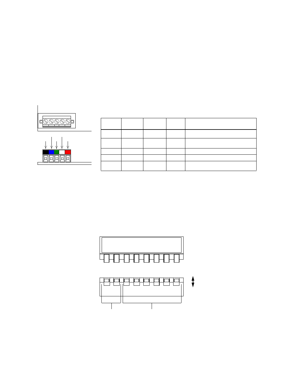
Wire the DeviceNet communication cable to the terminal block according to the following procedures:
Loosen terminal screws using a slotted screwdriver.
Strip about 5.5mm of insulation from the end of each DeviceNet wire and insert it into the corresponding terminal
according to the table and diagram below.
Secure wires by tightening terminal screws (Tightening torque: 0.22 ~ 0.25 [N ・ m]).
Tie the DeviceNet cable to a point near the terminal block to provide strain relief for the terminal block and cable
connection.
Note:
The shield is daisy chained between devices and should be grounded at the 24 V
dc
power supply as specified by
the Open DeviceNet Vendor Association (ODVA).
Set Baud Rate and Node Address
The option is equipped with one 8-bit DIP switch for baud rate and node address set-up. The DIP switches are located next to
the DeviceNet connector on the short side of the option. Set the network node address (MAC ID) by setting the DIP switches.
All devices on the network must have unique node addresses. Check the network layout to verify that the node address
selected is unique, falls between 3 and 62, and matches the master device configuration for that device. Node addresses 0 and
1 are typically reserved for master devices, while node address 2 is reserved for diagnostic/monitoring equipment, and address
63 for vendor-specific functions in some systems.
1
2
3
4
5
B K B L
W H R D
G R
BK GR RD
BL WH
Table 5: DeviceNet Terminal Block Connections
Terminal
No.
Terminal
Color
Name
Wiring
Color
Content
1
Black
V-
Black
Communication power supply GND
2
Blue
CAN_L
Blue
Communication data low side
3
Green
Shield
Bare
Shield wire
4
White
CAN_H
White
Communication data high side
5
Red
V+
Red
Communication power supply +24V
dc
DR
1
DR
0
ADR
5
ADR
4
ADR
3
ADR
2
ADR
1
ADR
0
1 2 3 4
8
5 6 7
OFF
ON
MAC ID Setting
Baud Rate Setting
Fig. 5 DIP Switch Settings for Baud Rate and Node Address