Baud rate setting switch, Table 6: baud rate dip switch setting, Mac id setting switch – Yaskawa DeviceNet Option Card CM059 User Manual
Page 16: Table 7: mac id switch setting, Termination resistors, Option indication leds, Fig. 7 devicenet status indication leds
16
Baud Rate Setting Switch
MAC ID Setting Switch
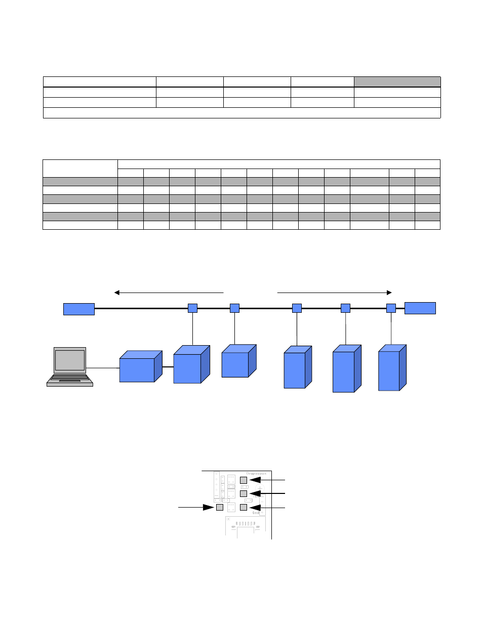
Termination Resistors
Terminating resistors must be mounted on the first and last node in a DeviceNet network, at both of the furthest ends of the
cable. The value of the Terminating resistor is specified by the ODVA (Open DeviceNet Vendors Association) and is a value of
121 Ohms, 1% tolerance, and ¼ watt. Terminating resistors can be found in the ODVA product catalog.
Fig. 6 Terminating Resistor Placement on DeviceNet Network
Option Indication LEDs
The option is equipped with four indication LEDs for module and DeviceNet status indication. The LEDs are located on the
option according to the figure below.
Table 6: Baud Rate DIP Switch Setting
Switch
500 kbps
250 kbps
125 kbps
Setting Prohibited
DR1
ON
OFF
OFF
ON
DR0
OFF
ON
OFF
ON
Note: If DR1 and DR0 are ON and set to Setting Prohibited, both MS and NS LEDs light up solid red.
Table 7: MAC ID Switch Setting
DIP Switch
MAC ID
0
1
2
3
4
5
6
7
8
・・・
62
63
ADR5
OFF
OFF
OFF
OFF
OFF
OFF
OFF
OFF
OFF
・・・
ON
ON
ADR4
OFF
OFF
OFF
OFF
OFF
OFF
OFF
OFF
OFF
・・・
ON
ON
ADR3
OFF
OFF
OFF
OFF
OFF
OFF
OFF
OFF
ON
・・・
ON
ON
ADR2
OFF
OFF
OFF
OFF
ON
ON
ON
ON
OFF
・・・
ON
ON
ADR1
OFF
OFF
ON
ON
OFF
OFF
ON
ON
OFF
・・・
ON
ON
ADR0
OFF
ON
OFF
ON
OFF
ON
OFF
ON
OFF
・・・
OFF
ON
R
R
RS-232 Interface
Module
Master
24Vdc
G5
F7
G7
Trunkline
Droplines
Terminating
Resistor
Terminating
Resistor
PLC/
Scanner
Power (PWR)
DeviceNet Module Status (MS)
DeviceNet Network Status (NS)
Option Status (WD)
Fig. 7 DeviceNet Status Indication LEDs