Setting jumpers, Install the module in the rack – ProSoft Technology MVI69-101S User Manual
Page 12
MVI69-101S ♦ CompactLogix or MicroLogix Platform
Start Here
IEC 60870-5-101 Slave Communication Module
Page 12 of 149
ProSoft Technology, Inc.
March 16, 2009
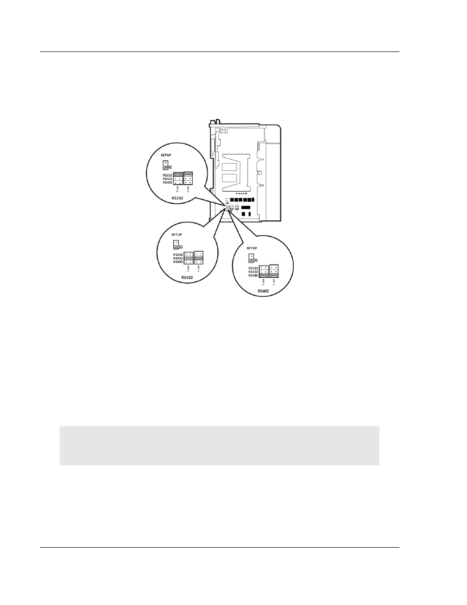
1.4 Setting
Jumpers
When the module is manufactured, the port selection jumpers are set to RS-232.
To use RS-422 or RS-485, you must set the jumpers to the correct position. The
following diagram describes the jumper settings.
The Setup Jumper acts as "write protection" for the module's flash memory. In
"write protected" mode, the Setup pins are not connected, and the module's
firmware cannot be overwritten. Do not jumper the Setup pins together unless
you are directed to do so by ProSoft Technical Support.
1.5
Install the Module in the Rack
This section describes how to install the module into a CompactLogix or
MicroLogix rack
Before you attempt to install the module, make sure that the bus lever of the
adjacent module is in the unlocked (fully right) position.
Warning: This module is not hot-swappable! Always remove power from the rack before
inserting or removing this module, or damage may result to the module, the processor, or other
connected devices.