ProSoft Technology MVI69-101S User Manual
Page 90
MVI69-101S ♦ CompactLogix or MicroLogix Platform
Reference
IEC 60870-5-101 Slave Communication Module
Page 90 of 149
ProSoft Technology, Inc.
March 16, 2009
Type ID
Type
Description
Data Representation
48 C_SE_NA_1
(7.3.2.4)
Setpoint Command, Normalized Value: This
command controls an analog device.
Normalized values (7.2.6.6) are stored in a
(16-bit) word data area with a range of -
1..+1-2
-15
49 C_SE_NB_1
(7.3.2.5)
Setpoint Command, Scaled Value: This
command controls an analog device.
Scaled values (7.2.6.7) are stored in a (16-
bit) word data area with a range of -2
15
..
+215
-1
A key concept in interfacing the protocol with the CompactLogix or MicroLogix
processor is the relationship between the databases and the data transfer
operation between the module and the processor. The module transfers data to
the processor in read blocks using the input image. These blocks should contain
the information received from the controlling unit (output data) and includes the
following data types: C_SC_NA_1, C_DC_NA_1, C_RC_NA_1, C_SE_NA_1 and
C_SE_NB_1.
This data is all sourced from the master unit and passed to the processor for
control. Databases associated with these data types should place the points in
the read data area of the module's database. The Read Register Start and Read
Register Count parameters in the configuration file establish the portion of the
database to transfer to the processor. Ladder logic extracts the data from the
read data area and places it in the proper location for use by the processor.
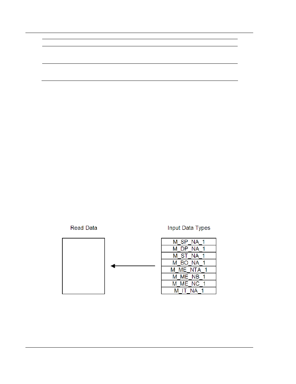
Similarly, data to be monitored (input data) by the master unit (all databases
associated with the "M_" data types) must all be placed in the write data area of
the module. The Write Register Start and Write Register Count parameters
establish the portion of the database to receive data from the processor. This
data is sourced from the processor and passed through the module to the remote
controlling unit. Ladder logic is required to place the data in the correct position in
the write data area. The relationship between the data types and the read and
write data areas is displayed in the following diagram: