Slave driver, Databases – ProSoft Technology MVI69-101S User Manual
Page 88
MVI69-101S ♦ CompactLogix or MicroLogix Platform
Reference
IEC 60870-5-101 Slave Communication Module
Page 88 of 149
ProSoft Technology, Inc.
March 16, 2009
Slave Driver
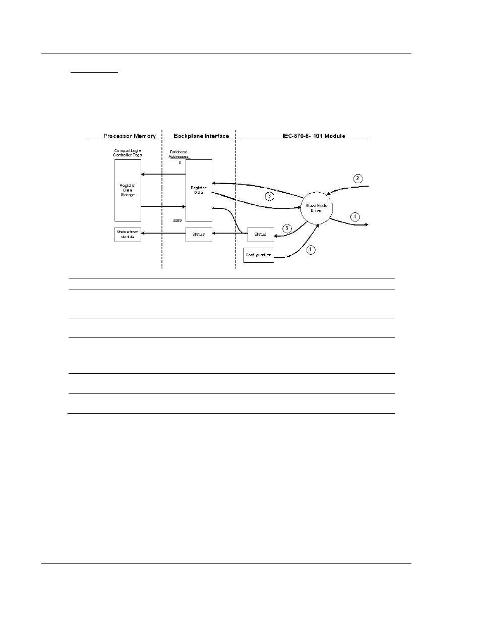
The Slave Driver allows the MVI69-101S module to respond to data read and
write commands issued by a master unit on the telecontrol network. The
following flow chart and associated table describe the flow of data into and out of
the module.
Step Description
1
The slave port driver receives the configuration information from the Compact Flash Disk in
the module. This information configures the serial port and define the slave node
characteristics.
2
A Host device issues a read or write command to the module's node address. The port
driver qualifies the message before accepting it into the module.
3
After the module accepts the message, the data is immediately transferred to or from the
internal database in the module. If the command is a read command, the data is read out of
the database and a response message is built. If the command is a write command, the
data is written directly into the database and a response message is built.
4
After the data processing has been completed in Step 3, the response is issued to the
originating master node.
5
Counters are available in the Status Block that permit the ladder logic program to determine
the level of activity of the Slave Driver.
Review the Installing and Configuring the Module section for a complete list of
the parameters that must be defined for a slave port. The IEC 60870-5-101
Interoperability Document for the MVI69-101S Slave Module contains a listing of
the protocol support supplied in the module.
5.2.7 Databases
The read and write areas can be placed anywhere in the module's database
area. Because each point is defined individually to the module, the data for a
specific type need not be contiguous in the module's database. This means that
the module error/status data area can be passed to the controlling station using
the M_ME_NB_1 database. In the database definition for the type, establish a
point for each status value to be monitored by the controlling station and set the
module's database address for the point in the definition.