Solid State Logic SSL 12 USB Audio Interface User Manual
Page 9
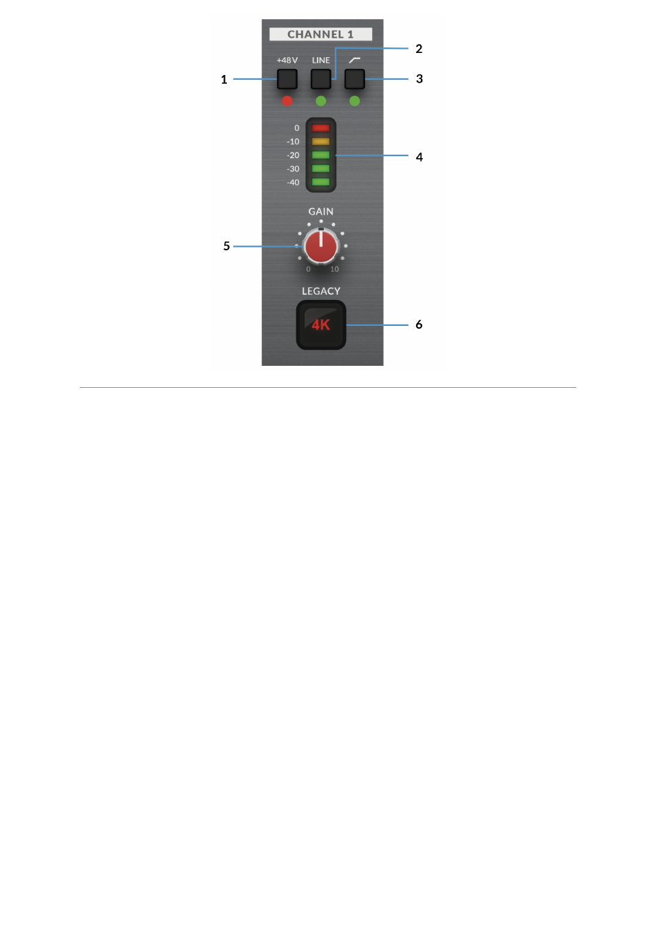
This section describes the controls for Channel 1. The controls for Channels
2-4 are exactly the same.
1. +48V
This switch enables phantom power on the combo XLR connector, which will be
sent down the XLR microphone cable to the microphone. When
engaging/disengaging +48V, the LED blinks a couple of times and the audio is
temporarily muted to avoid any unwanted audio clicks/pops. Phantom power is
required when using Condenser microphones or certain active Ribbon mics.
Dynamic or Passive Ribbon microphones do not require phantom power to operate,
and in some cases can cause damage to the microphone. If in doubt, make sure
+48V is off before plugging in any microphone and consulting the user manual from
the manufacturer to ensure correct operation
2. LINE
This switch changes the source of the channel input to be from the balanced Line
input. Connect line-level sources (such as keyboards and synth modules) using a
TRS Jack cable into an input on the rear panel.
3. HI-PASS FILTER
This switch engages the Hi-Pass Filter with a cut off frequency at 75Hz with a
18dB/Octave slope. This is ideal for removing unwanted low-end frequencies from
an input signal and cleaning up unnecessary rumble. This is suitable for sources
such as Vocals or Guitars.
4. LED METERING