Checking commlink network loop – cv-ex, Diagram, Overview – Auto-Zone Control Systems Auto-Zone CV & CV-EX Systems Installation & Operation (Version 01C) User Manual
Page 102: Measurements, Action, Network loop acceptable range, Condition action
Section 4
Auto-Zone CV & CV-EX
4-24
Start-Up and Troubleshooting
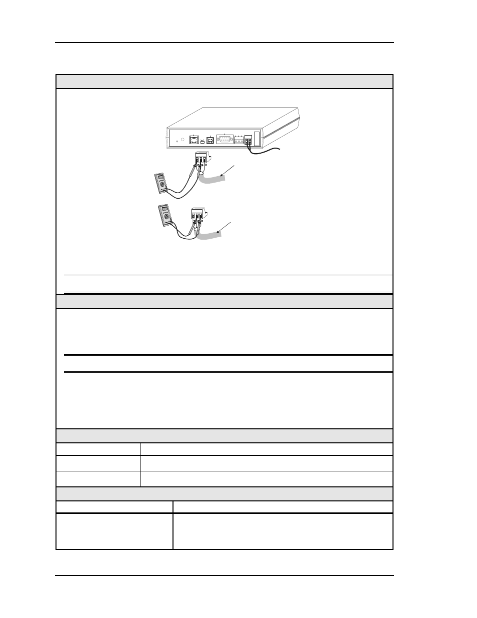
Checking CommLink Network Loop – CV-EX
Diagram
Set Your Meter
To Read DC Volts
+
-
+
-
Communications
Loop
Disconnected
Communications
Loop
Disconnected
+
-
T-To-G
+2.4 VDC
To
+3.3 VDC
R-To-G
+2.4 VDC
To
+3.3 VDC
CommLink IV
To 24 VAC
Power Supply
MODEM
RS-232
Serial #
COMPUTER
USB
10/100
ETHERNET
DIAG
24
V
T G R
GN
D
485 LOOP POWER
ACT
LNK
USB
Co
n
fi
g
No
rm
al
The CommLink IV Must Be
Powered Up For These Tests
+
-
The indicated values are typical of a normal system; actual readings may deviate slightly
due to the number of units connected and other system specific factors.
Note: All of the connected CV controllers should be powered up for this test.
Overview
This is a “quick check” to determine if any of the driver chips on the Network loop are
damaged. Since all units will “float” both of their communications connections at about
2.45 Volts, you can quickly check the entire Network loop by unplugging it at the
CommLink IV.
Note: Be sure that the loop you are testing does not have a short circuit from T to R.
Tip: The Loop LED (located on the front panel) should “flicker” when the CommLink is
attempting to communicate with the MiniLinks. There is a noticeable change in the
flicker when the loop is disconnected if you observe a normal functioning unit. When
the loop is reconnected, it may take up to 60 seconds before the CommLink
re-establishes communications with the MiniLinks.
Measurements
Network Loop
Acceptable Range
T - G (SHLD)
2.4 - 3.3 Volts DC
R - G (SHLD)
2.4 - 3.3 Volts DC
Action
Condition
Action
If voltages are too high or
too low on either side.
1. One or more of the MiniLinks has a damaged Network
driver chip. Disconnect one at a time to isolate the prob-
lem. See Figure 4-10.