Minilink interface wiring, Figure 2-19: minilink interface wiring – Auto-Zone Control Systems Auto-Zone CV & CV-EX Systems Installation & Operation (Version 01C) User Manual
Page 37
Auto-Zone CV & CV-EX
Section
2
Installation and Wiring
2-25
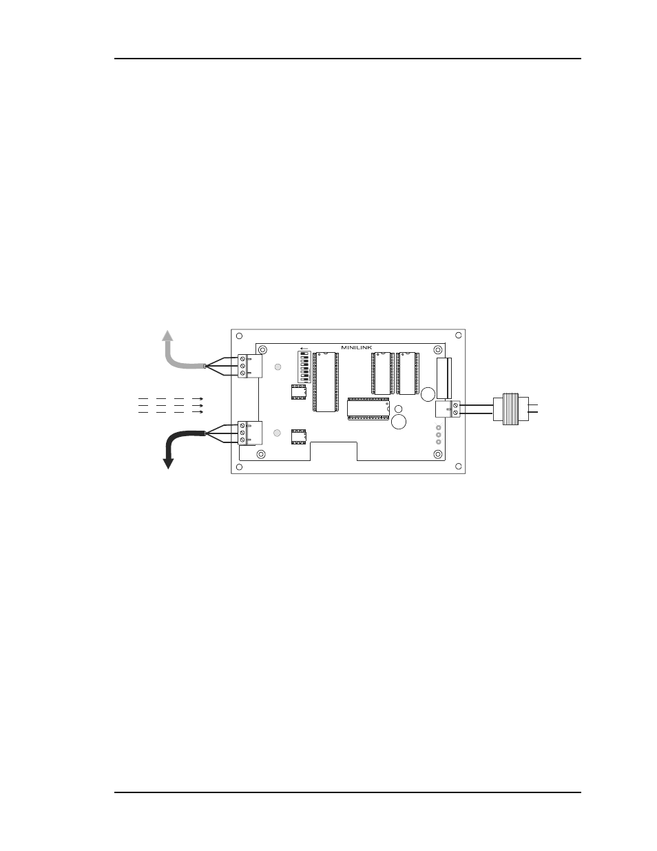
MiniLink Interface Wiring
All MiniLinks on the CV-EX system must be wired to each other with a Network
communications loop, daisy-chaining the Network loop terminals together. One end of
the CV-EX system Network loop must be connected to the CommLink IV interface. Each
MiniLink on the CV-EX system is then wired from its Local loop terminals to the CV
Controllers on that Local loop. The MiniLink also requires 24 VAC power to operate.
Each MiniLink must be addressed from 1 to 4 with a unique address. The addresses are
set with the address switch at each MiniLink board. See Figure 2-18 for the address
switch location. See Figure 2-19 for wiring information.
R
SH
T
R
SH
T
R
SH
T
R
SH
T
All Communication Loop
Wiring Is Straight Through
Required VA For Transformer
MiniLink = 10VA Max.
See Note 1.
LO
O
P
24VAC
GND
T
SH
R
32
16
8
4
1
2
OFF >
Local Loop
RS-485
9600 Baud
(See Note 3).
Connect To CV
Controller or
System Manager
On Local Loop
Connect To Next
MiniLink And/Or
CommLink On
Network Loop
Network Loop
RS-485
19200 Baud
(See Note 3).
Line Voltage
24VAC
GND
MiniLink Communications Interface
ADD
NETWORK
SH
T
R
Notes:
1.)24 VAC Must Be Connected So
That All Ground Wires Remain
Common.
2.)All Wiring To Be In Accordance
With Local And National Electrical
Codes And Specifications.
3.) All Communication Wiring To Be
2 Conductor Twisted Pair With
Shield. Use Belden #82760 Or
Equivalent.
Figure 2-19:
MiniLink Interface Wiring