Driver chip replacement, Figure 4-10: driver chip locations, Minilink – Auto-Zone Control Systems Auto-Zone CV & CV-EX Systems Installation & Operation (Version 01C) User Manual
Page 113
Auto-Zone CV & CV-EX
Section 4
Start-Up and Troubleshooting
4-35
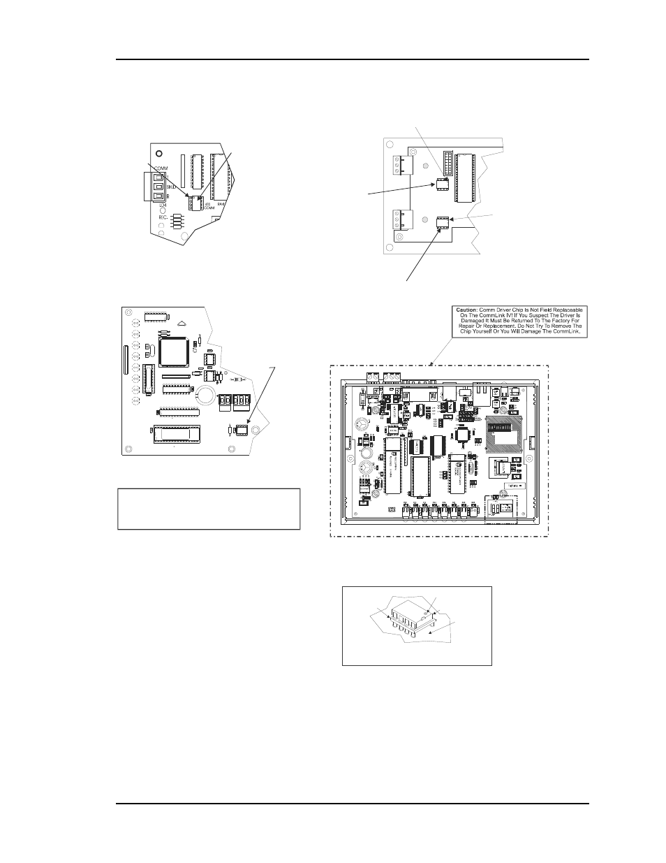
Driver Chip Replacement
Pin 1
Dot
Socket
Printed
Circuit
Board
Typical RS-485
Communications
Driver Chip Detail
System Manager
CommLink IV
Comm Driver Chip
(U12)
CV Controller, CV-EX Controller
GPC Plus Controller, Wetbulb Controller
Pin 1
Pin 1
Pin 1
Comm Driver Chip
( U5 )
1.) Be Sure That Any Small Screwdriver Or Other
Sharp Object Used To Remove The Chip Does Not
Come Into Contact With The Printed Circuit Board
Surface.
2.) A Small Screwdriver May Be Inserted Between The
Chip And The Socket To Aid In Removal Of The Chip.
3.) Be Very Careful Not To Insert The Screwdriver Under
The Socket!! Damage To The Board Is Not Covered
By Warranty.
LOO
P
32
16
8
4
1
2
NE
T
W
O
RK
Network Loop
Comm
Driver Chip
Local Loop
Comm
Driver Chip
T
SH
R
T
SH
R
MINILINK
Warning!
Use Extreme Caution When Removing Any Chips
To Avoid Damaging Any Circuit Board Traces Which
Are Under The Chip.
Notes:
24
V
A
C
GN
D
SH
LD
EPR
O
M
SYSTEM MANAGER
YS101806 REV. 1
U13
CX
13
R1
0
CX
12
U12
L1
RN
1
U2
C3
U6
CX7
CX
9
U7
S
Y
S
48K
2V
U9
U8
CX
8
RN2
X2
C2
C1
X1
CX
4
U4
R2
R1
EW
D
O
G
R3
SC1
T
TB
1
R
TB
2
D3
U5
CX5
U1
CX
1
ALTERA
EPM3032
WattMaster Controls Inc.
COMMLINK IV
YS102074
REV6
MADE IN USA
MiniLink
Figure 4-10: Driver Chip Locations