System manager, Ph il ip s, System manager top – Auto-Zone Control Systems Auto-Zone CV & CV-EX Systems Installation & Operation (Version 01C) User Manual
Page 85: System manager base
Auto-Zone CV & CV-EX
Section 4
Start-Up and Troubleshooting
4-7
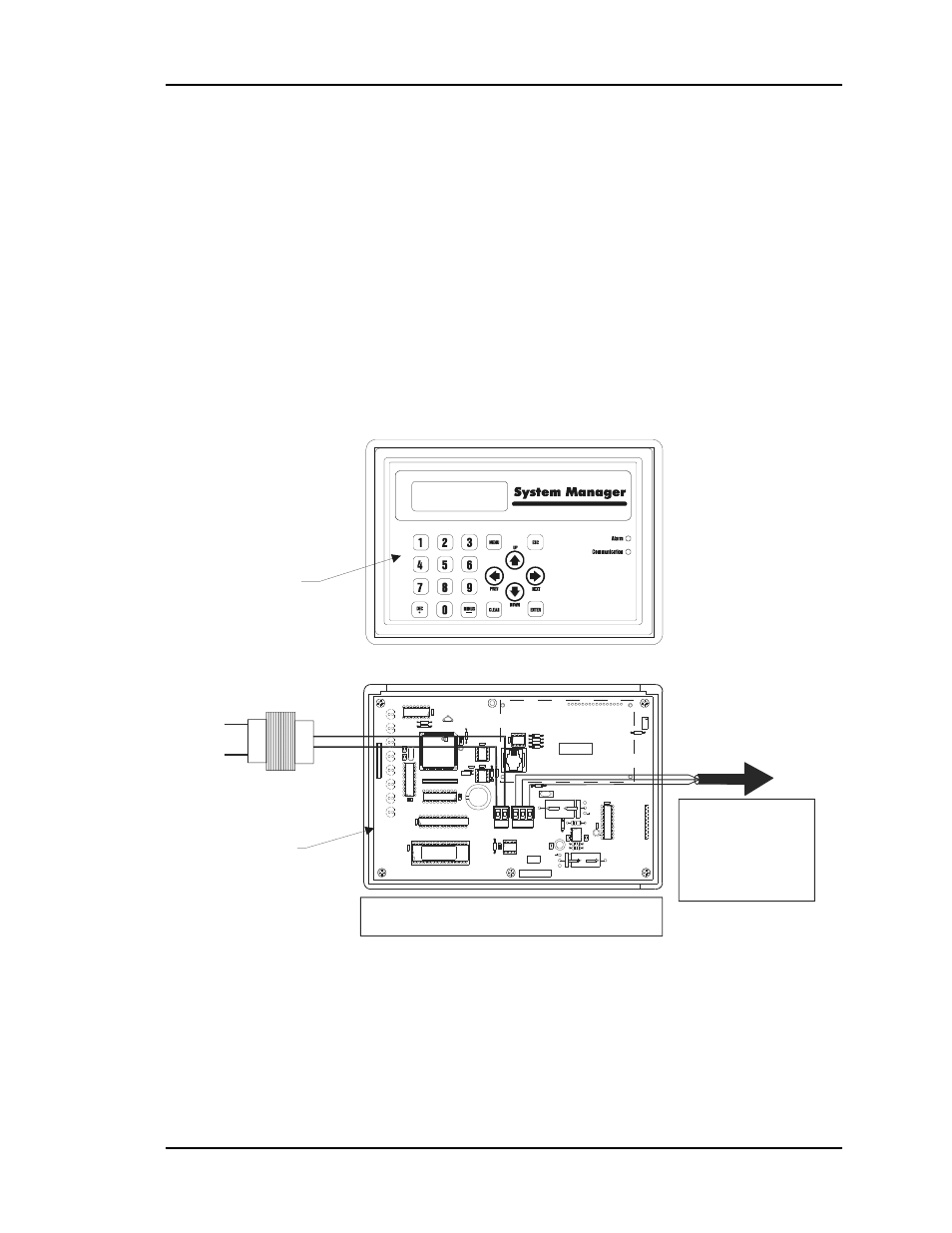
System Manager
The System Manager is the central operator interface for the CV or CV-EX system. It
must also be connected correctly to the communications loop in order to view the system
status and configure or change setpoints. It must be supplied with 24 VAC power in order
to operate. The System Manager does not require addressing. The System Manager is
always connected to the “Local” loop. For the CV system, this is the only loop on the
system. The System Manager can be connected anywhere on the CV communications
loop. In contrast, the CV-EX has two types of loops—the “Network” and “Local” loops.
The System Manager must be connected to the local loop on the CV-EX system. It will
not function correctly if connected to the network loop! See Figure 4-6 for wiring and
component location information for the System Manager.
Notes:
1.) 24 VAC Must Be Connected So
That All Ground Wires Remain
Common.
2.) All Wiring To Be In Accordance
With Local And National Electrical
Codes And Specifications.
3.) All Communication Wiring To Be
2-Conductor Twisted Pair With
Shield. Use Belden #82760 Or
Equivalent.
Line Voltage
See Note 1
See Note 3
24VAC
GND
Required VA For Transformer
System Manager = 25VA Max.
MADE IN
THE USA
EP
R
O
M
1000uF10v
YS101806 REV. 1
DSPY1
UNIVERSAL SMART DISP. UNIT
SYSTEM MANAGER
SERIAL # :
U13
SERIAL #
1000uF10v
C9
470u
F50
v
D2
P
C
B
80C
55
2-
5-
16W
P
4428
60=
2/
5
D
fD
9
722
V
7
Y
PH
ILIP
S
CX
13
LD8
CX
9
SS0017
vx.xx 1234
V62C518256L-70P
U9
U8
LD7
RN
1
LD6
U7
CX7
74H
C
573
LD5
LD4
74H
C573
CX
8
RN2
X2
CX
4
470uF50
v
TB
2
GN
D
24V
A
C
R1
0
75176
RS-485
COMM
U12
CX
1
2
RA
M
SC1
T
TB
1
SH
L
D
C7
C1
1
L1
C4
R
D6
8583
U6
CX6
C3
D3
24C
128
U5
R7
VAR1
D4
PJ
1
R3
U1
74HC
259
LD3
LD2
LD1
R2
R1
EW
D
O
G
PH
IL
IP
S
U3
U2
CX
1
82B715
CX5
CX
3
U3
DSPY1
R5
D1
R6
M
C
340
64A
C6
R11
9
936
C8
R9
U10
U11
R8
R12
C5
74H
C
92
3
CX10
P1
R4
RV1
C2
C1
X1
The Ideal Recommended Location For The System Manager Is As The First
Device On The Local Loop. The System Manager May Be Connected To The
Local Loop At Any Point On The Local Loop.
For CV Systems, Connect To Any
CV Controller On The Local Loop
Or To The CommLink. For The
CV-EX System, Connect To Any
Controller On The Local Loop Or
To The Local Loop Terminal On
The MiniLink.
Do Not Connect To The
Network Loop On CV-EX
Systems!
System Manager
Top
03/20/09 06:38PM FRI
OCCUPIED
NO ALARMS
System Manager
Base
Figure 4-6:
System Manager Component Location & Wiring