Checking cv controller drivers – cv & cv-ex, Diagram meter set to read dc volts, Overview – Auto-Zone Control Systems Auto-Zone CV & CV-EX Systems Installation & Operation (Version 01C) User Manual
Page 109: Measurements, T - shld, R - shld, Action
Auto-Zone CV & CV-EX
Section 4
Start-Up and Troubleshooting
4-31
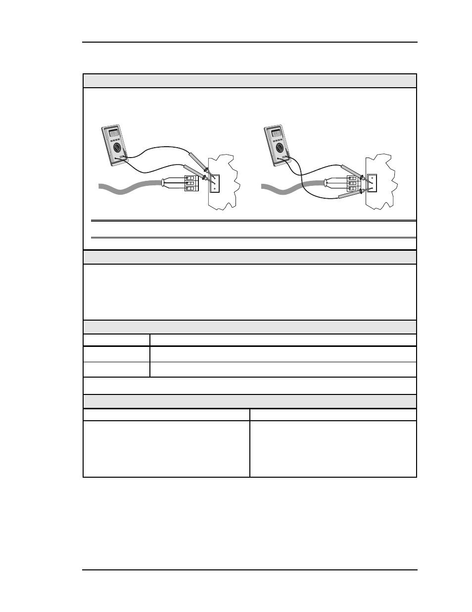
Checking CV Controller Drivers – CV & CV-EX
Diagram
Meter Set To Read DC Volts
T to SHLD
CV Controller
CV Controller
R to SHLD
+
-
T
R
SHLD
+
-
+2.4 VDC
to
+3.3 VDC
COMM
LOOP
T
SHLD
R
+
-
T
R
SHLD
+
-
+2.4 VDC
to
+3.3 VDC
COMM
LOOP
T
SHLD
R
Note: These tests assume that the CV controller being checked is powered up.
Overview
This check is intended to determine if the Comm Driver chip on a controller is damaged.
Damage typically occurs when the communications loop is exposed to excessive voltage as
may occur during installation due to wiring errors. The driver chips are socketed on all
boards to facilitate servicing. It is unusual for driver chips to fail during normal operation.
Almost all failures occur as a result of wiring-related problems.
Measurements
Local Loop
Acceptable Range
T - SHLD
2.4 – 3.3 Volts DC
R - SHLD
2.4 – 3.3 Volts DC
Note: Minor variances may not indicate a problem if both tests indicate similar values.
Action
Condition Action
If voltages are too high or too low on either
side.
The controller has a damaged Comm
Driver chip. Replace the driver chip. See
instructions for "CV Controller Driver
Chip Replacement.” See Figure 4-10 &
4-11.