Stereo generator connections, Comp 1 & comp 2 (composite outputs 1 & 2) (bnc), 19 khz out (pilot sync output) (bnc) – Omnia Audio Omnia.11 User Manual
Page 20: Sca input (bnc), Sca in lvl (sca input level) (trimpot adjustment)
4
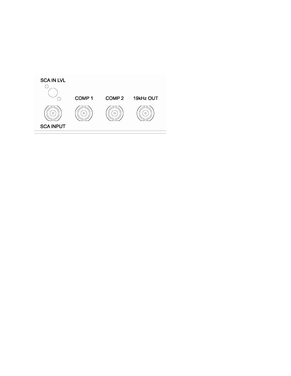
Stereo Generator Connections
Four standard female BNC connectors comprise the Omnia.11’s stereo generator connections.
There are two composite MPX outputs with independent software level controls, one SCA input with level adjust
trimpot and one 19 kHz pilot sync output.
COMP 1 & COMP 2 (Composite Outputs 1 & 2) (BNC)
These two low impedance outputs (Composite 1 and Composite 2) are each capable of driving up to 100 feet of
RG-58A/U coax cable. The output levels are individually adjustable so the unit can operate as a “composite
DA” to drive a variety of equipment. The output levels and other stereo generator settings are set through
software parameters in the Composite submenu of the Output menu. An internal jumper sets the output
impedance to either 5 ohms (the factory setting) or 75 ohms. The default setting is appropriate for the vast
majority of exciter connections. However, in the event that a higher source impedance is required, a jumper can
be moved (one for each composite output) on the motherboard to change the source impedance to 75 ohms. For
reference, JP10 is for Composite #1, and JP9 is for Composite #2.
Jumpers JP7 & JP8 are also available if you need to limit the maximum peak-to-peak output voltage from the
composite outputs to 4v p-p instead of the normal 10v p-p. They default to the Normal (10v p-p) setting.
19 kHz OUT (Pilot Sync Output) (BNC)
This TTL-level 19 kHz square wave output can be used as the reference signal for most RDS or SCA generators
that operate at 57 kHz or other multiple of the 19 kHz pilot frequency. This Sync output is phase and frequency
locked to the stereo pilot. When this signal is used to synchronize an external SCA or RDS generator, this
locking assures that no difference frequencies exist which may cause intermodulation between the pilot and the
SCA signal.
SCA INPUT (BNC)
Any SCA or RDS signal above 53 kHz can be added to the composite outputs of the Omnia.11 by connecting
the signal to the SCA INPUT connector. The SCA signal is mixed in the analog domain directly into both
composite outputs. A high-pass filter on the SCA input provides SCA to main-channel crosstalk protection. The
SCA injection level can be adjusted using the SCA IN LVL control trimpot. See below for details.
SCA IN LVL (SCA Input Level) (trimpot adjustment)
Located just above the SCA Input BNC jack is the SCA IN LVL (SCA Input Level) adjustment control.
Carefully insert a small bladed screwdriver into the hole and adjust the control if needed to set the SCA
injection level.