Block diagram, Wide band – Omnia Audio Omnia.11 User Manual
Page 61
45
Block Diagram
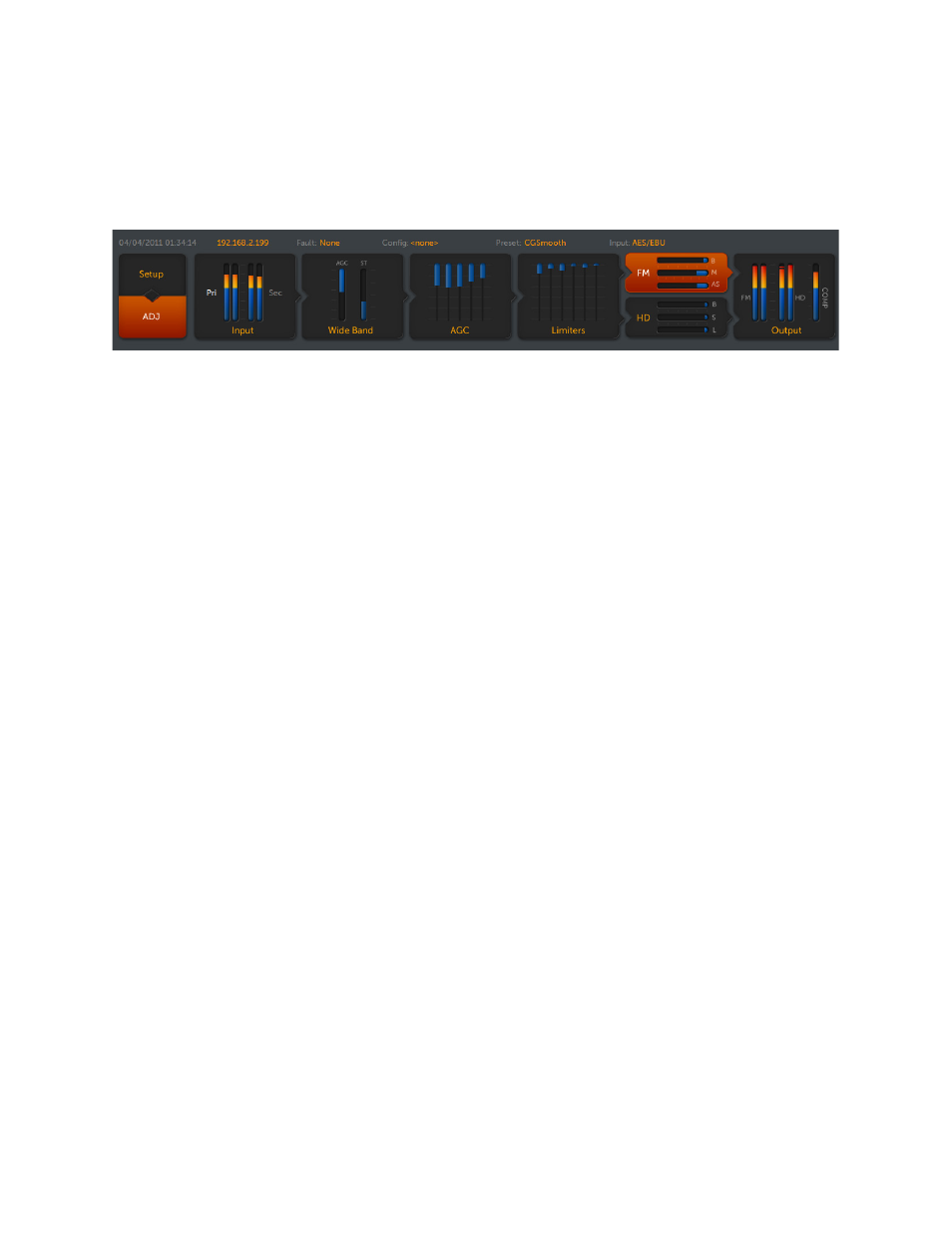
If you look closely at the Icon Buttons at the top of the Omnia.11’s screen, you will see that they form a block
diagram or flow chart of the processing path your audio takes through the fully digital, DSP based processing stages
within the Omnia.11:
Icon Buttons
The audio starts at the Input section where input sources are selected and levels are set. The audio then goes to the
first processing stage, the Wide Band AGC (automatic gain control). Next up is a 5-Band AGC section, a 6-Band
peak Limiter section with its own crossover and the final, separate peak control sections for the FM and HD
channels. Lastly is the Output section where the channels are routed to their selected output jacks and levels are set.
Wide Band
The Wide Band AGC section is the first processing section the audio “sees” as it passes from the Input section.
The job of the Wide Band AGC is to act as a very smart “hand on the pot”, ensuring that quiet intros (for example)
do not get “lost” or that loud program sections do not over-drive the following 5-Band AGC section.
Adjustments here can be found in both the Basic and Advanced tabs and are discussed fully in the next section.
First, a few important notes about the WB AGC in the Omnia.11 since it is different than what has come before:
We designed the AGC with very active programming in mind.
Make sure your input levels on the processor are set properly (per the instructions earlier in this guide) and are
hitting up to around -15 dB on the Input Meters (just into the yellow) when your incoming program levels are
normal. (For analog boards this would be “0dB” or “0VU” and for digital boards this would be when the metering
on the Omnia.11 is matching what your digital console is showing on its metering).
In other words, with normal program audio playing, if the analog console’s meters are bouncing up to 0VU (or the
digital console’s meters are hitting -15 dBFS), the Omnia.11’s Input meters should show about -15dB. If they are,
you're good to go!
As for the AGC, you can drive it very heavily if you want. It won't care. It will not change its sound characteristics
no matter how heavily it is being driven (up to -30 dB). In other words there is no “sweet spot” to get the best sound.
On the “normal” program levels described above, it should generally average around -12 to -18 dB or so on the WB
AGC vertical gain-reduction meter (described in the Wideband AGC Metering section below).
Using higher compression ratios (a Ratio setting in the Advanced tab of 7:1 or higher) will minimize any level
variation coming from the studio. The trade-off is a more "closed in" sound when using the highest settings. Some
programmers desire this effect for CHR programming, so it's just a matter of programming taste.
Medium ratios of about 4:1 or 5:1 preserve a bit more of the natural dynamics in the source material while still
“riding the gain” very well. A ratio of 2:1 is used primarily to provide maximum preservation of natural dynamics
on very wide dynamic range program material such as Classical.