Synchronization, Preamble – Wavecom W-BitView V2.5.00 User Manual
Page 34
28
Function Library
BitView Manual V2.5.00 WAVECOM W-BV
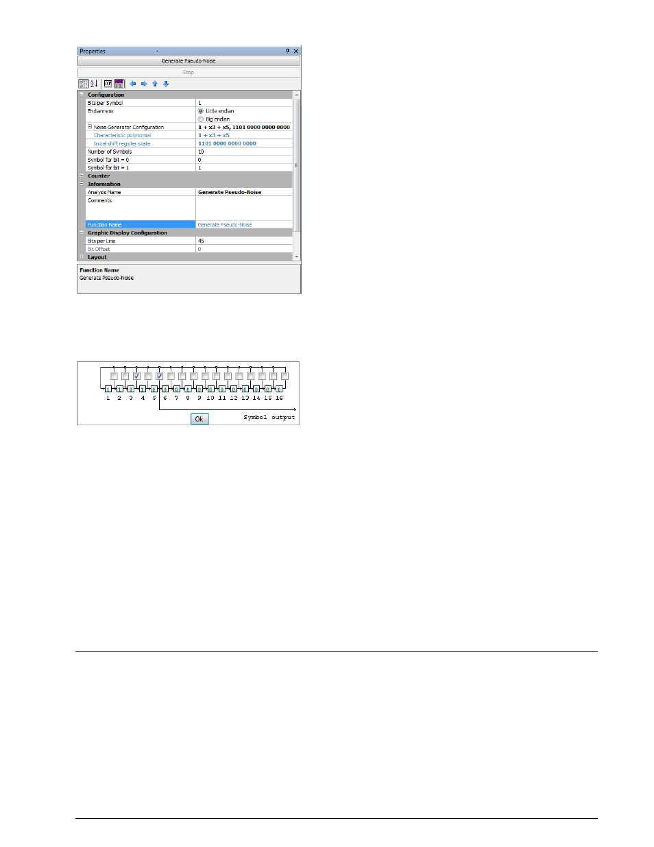
Function:
Generate a pseudo-random noise symbol sequence using a linear feedback shift register initialized with a
bit pattern (seed). The shift register is configured by clicking the Noise Generator Configuration field.
Clicking the drop-down list will open a shift register schematic with 16 stages, each representing in
increasing order the elements of the characteristic polynomial of the shift register:
A click in the check box for each stage enables that bit (the initial term x
0
= 1 is omitted). Clicking a stage
box will toggle its initial state between 1 and 0. When configuring the shift register setting is complete
click Ok to save the configuration, which is displayed in the Characteristic polynomial and Initial shift
register state fields.
The Number of Symbols determines the length of the pseudo noise output string.
The shift register output bits are mapped to symbols defined by Symbol for bit = 0 and Symbol for bit
= 1. The settings must reflect the specific coding of the mode for which the sequence is generated, e.g.,
for STANAG-4285 the settings must reflect the values of the transcoding tables of STANAG-4285 (see
custom function “Symbol Transcoding”).
When configuration is finished, press the Generate Pseudo-Noise buttonto generate the desired
sequence – pressing Stop terminates the generator. The generated string appears in the document
window as well as in the graphical display and as a line of raw bits.
This function allows the user to automatically generate a correct shift register based bit sequence and
then use it as a search string by pasting the generated sequence into one of the Highlighting text bins
(Highlighting Bitfield 0 … 3) in the Bit & Text Display Configuration category.
Synchronization
Preamble
In: Bit stream
Out: Bit stream