Wiring power inputs – Westermo MDI-112-F4G User Manual
Page 10
6
2.2
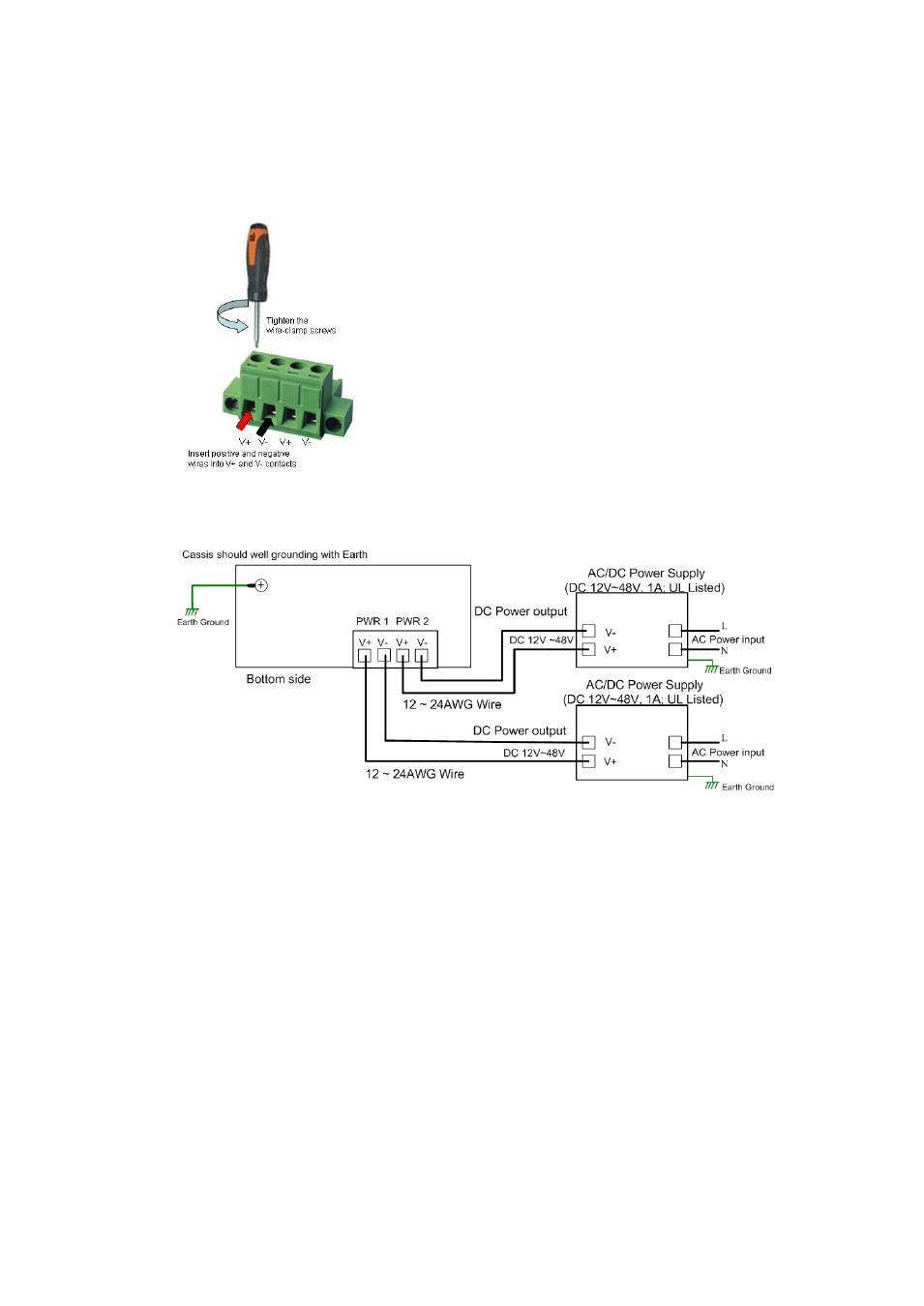
Wiring Power Inputs
DC Power Input
Follow below steps to wire the redundant DC power inputs.
1. Insert positive and negative wires into V+ and
V- contacts respectively of the terminal block
connector
2. Tighten the wire-clamp screws to prevent DC
wires from being loosened.
3. Power 1 and Power 2 support power
redundancy and polarity reverse protection
functions.
4. Positive and negative power system inputs are
both accepted, but Power 1 and Power 2 must apply the same mode.
Note 1: It is a good practice to turn off input and load power, and to unplug
power terminal block before making wire connections. Otherwise, your
screwdriver blade can inadvertently short your terminal connections to the
grounded enclosure.
Note 2: The range of the suitable DC electric wire is from 12 to 24 AWG.
Note 3: If the 2 power inputs are connected, the switch will be powered from the
highest connected voltage. The unit will alarm for loss of power, either POWER1
or POWER2.
Note 4: Use a UL Listed Power supply with output rating 12-48VDC, minimum
1 A.