Cooling – H3C Technologies H3C S7500E Series Switches User Manual
Page 16
Advertising
5
Cooling
For adequate heat dissipation, plan the installation site according to the airflow of your switch, and
adhere to the following requirements:
•
Leave a clearance of at least 10 cm (3.94 in) around the air intake and exhaust vents.
•
The rack for installing the switch has a good cooling system.
•
The installation site has a good cooling system.
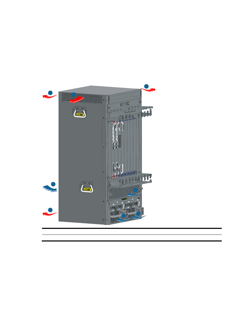
Figure 1 Airflow for the S7506E-V
(1) Air intake for power modules
(2) Air exhaust for power modules
(3) Air intake for the chassis
(4) Air exhaust for the chassis
1
1
2
3
3
4
4
4
Advertising