Cable management requirements – H3C Technologies H3C S7500E Series Switches User Manual
Page 161
150
Cable management requirements
•
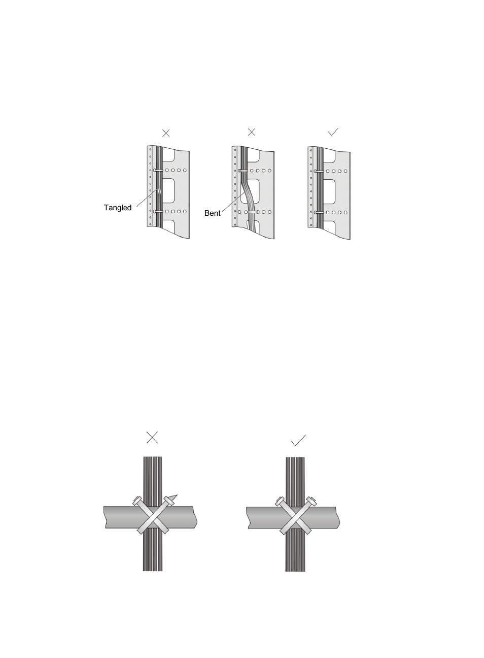
Bind and put the cables inside the rack in an organized manner. Make sure the cables do not have
any kinks or sharp bends.
Figure 70 Cable binding example 1
•
Different cables (power, signal, and PGND cables) should be routed and bound separately rather
than together in the rack. If they are close to each other, you can route them in cross-shape. For
parallel routing, the space between power cable and signal cable should be no less than 30 mm
(1.18 in).
•
The cable management bracket and cable routing slot inside and outside the rack should be
smooth and without sharp edges or tips.
•
The metal cable management hole should have a smooth and fully rounded surface or wear an
insulating bush.
•
Use the right type of ties to bind the cables. Do not bind cables with joined ties. The following types
of ties are available currently: 100 × 2.5 mm (3.94 × 0.10 in), 150 × 3.6 mm (5.91 × 0.14 in), 300
× 3.6 mm (11.81 × 0.14 in), 530 × 9 mm (20.87 × 0.35 in), and 580 × 13 mm (22.83 × 0.51 in).
•
Cut the extra parts of the ties neatly after binding the cables, leaving no sharp or angular tips. See
the following figure:
Figure 71 Cable binding example 2