Connecting the psr320-a/psr650-a, Connecting the psr1400-a power cable – H3C Technologies H3C S7500E Series Switches User Manual
Page 36
25
make that the AC power supply system can provide enough power. For the power cables used in different
countries or regions, see "Pluggable module ordering guide."
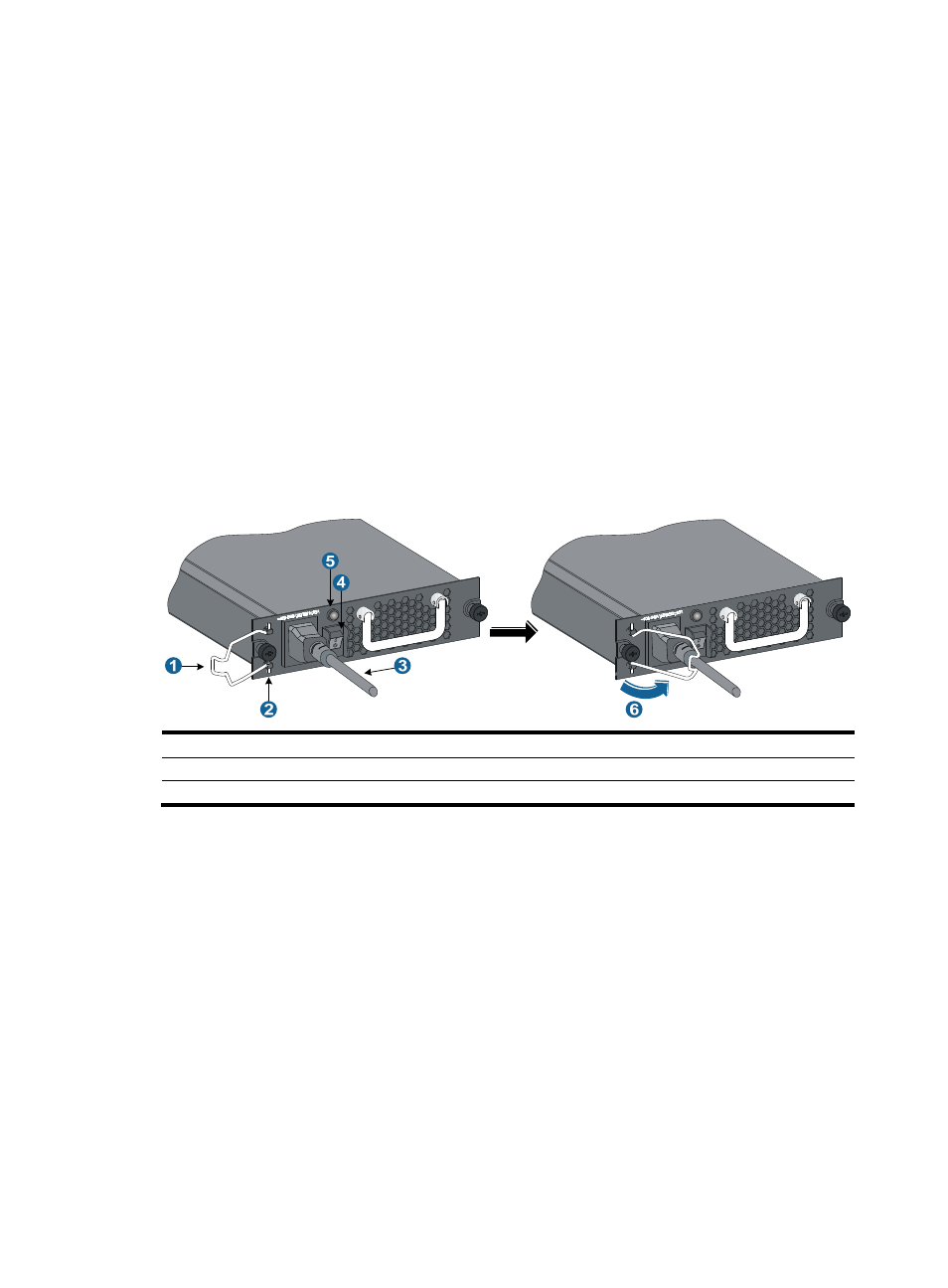
Connecting the PSR320-A/PSR650-A
1.
Install a bail latch on the power module. Insert the two ends of the bail latch to the slots on the left
of the power socket. Then pull the bail latch to the left.
2.
Unpack the power cable, and make sure of the power cable model (both the PSR320-A and
PSR650-A use a 10 A AC power cable).
3.
Plug the power cable to the power socket, and ensure a good contact.
4.
As shown in callout 6 on
, pull the bail latch to the right to retain the power cable.
5.
Plug the other end of the power cable to the AC power socket.
6.
Switch on the power module.
7.
Verify the power module status LED. If the LED is green, the power cable is correctly connected. If
the LED is off or red, power off the power module, verify the installation, and solve the problem.
Then switch on the power module and verify that the LED is green. For description of
PSR320-A/PSR650-A status LEDs, see "
."
Figure 22 Connecting the PSR320-A/PSR650-A power cable
(1) Bail latch
(2) Bail latch slot
(3) Power cable
(4) Power switch (O: off; —: on)
(5) power module LED
(6) Pull the bail latch to the right to retain the power cable
Connecting the PSR1400-A power cable
1.
Unpack the power cable, and make sure of the power cable model (the PSR1400-A uses a 16 A
AC power cable).
2.
Use a Phillips screwdriver to remove the screws from the power cable retainer suite and remove the
right part of the retainer suite.
3.
Plug the power cable to the power socket on the power module, and ensure a good contact.
4.
Fasten the right part of the power cable retainer to lock the power cable.
5.
Plug the other end of the power cable to the AC power socket.
6.
Verify the power module input status LED (INPUT).
If the LED is green, the power cable is correctly connected. If the LED is off or red, verify the
installation, and solve the problem. Then switch on the power module to verify that the LED is green.
For description of PSR1400-A status LEDs, see "
."