Configuration procedure – H3C Technologies H3C WX3000E Series Wireless Switches User Manual
Page 171
160
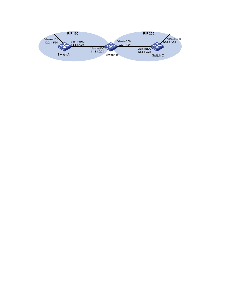
Figure 56 Network diagram for RIP route redistribution configuration
Configuration procedure
1.
Configure an IP address for each interface (Omitted).
2.
Configure basic RIP functions.
# Enable RIP 100 and specify RIP version 2 on Switch A.
<SwitchA> system-view
[SwitchA] rip 100
[SwitchA-rip-100] network 10.0.0.0
[SwitchA-rip-100] network 11.0.0.0
[SwitchA-rip-100] version 2
[SwitchA-rip-100] undo summary
[SwitchA-rip-100] quit
# Enable RIP 100 and RIP 200 and specify RIP version 2 on Switch B.
<SwitchB> system-view
[SwitchB] rip 100
[SwitchB-rip-100] network 11.0.0.0
[SwitchB-rip-100] version 2
[SwitchB-rip-100] undo summary
[SwitchB-rip-100] quit
[SwitchB] rip 200
[SwitchB-rip-200] network 12.0.0.0
[SwitchB-rip-200] version 2
[SwitchB-rip-200] undo summary
[SwitchB-rip-200] quit
# Enable RIP 200 and specify RIP version 2 on Switch C.
<SwitchC> system-view
[SwitchC] rip 200
[SwitchC-rip-200] network 12.0.0.0
[SwitchC-rip-200] network 16.0.0.0
[SwitchC-rip-200] version 2
[SwitchC-rip-200] undo summary
# Display the routing table of Switch C.
[SwitchC] display ip routing-table
Routing Tables: Public
Destinations : 6 Routes : 6
Destination/Mask Proto Pre Cost NextHop Interface
12.3.1.0/24 Direct 0 0 12.3.1.2 Vlan200
12.3.1.2/32 Direct 0 0 127.0.0.1 InLoop0
16.4.1.0/24 Direct 0 0 16.4.1.1 Vlan400