Configuration procedure – H3C Technologies H3C WX3000E Series Wireless Switches User Manual
Page 185
174
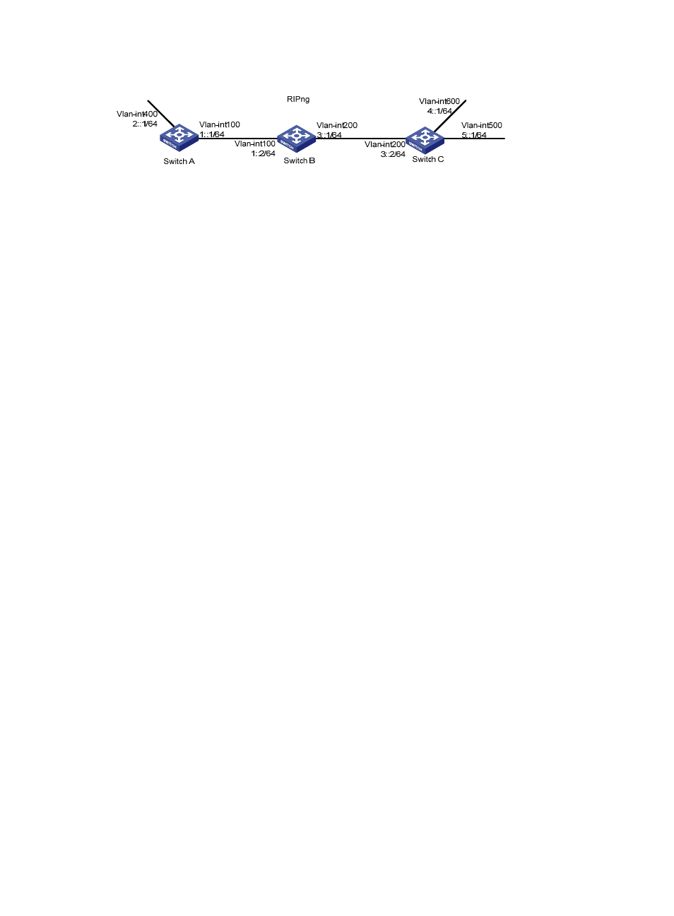
Figure 61 Network diagram for RIPng configuration
Configuration procedure
1.
Configure the IPv6 address for each interface (omitted)
2.
Configure basic RIPng functions
# Configure Switch A.
<SwitchA> system-view
[SwitchA] ripng 1
[SwitchA-ripng-1] quit
[SwitchA] interface vlan-interface 100
[SwitchA-Vlan-interface100] ripng 1 enable
[SwitchA-Vlan-interface100] quit
[SwitchA] interface vlan-interface 400
[SwitchA-Vlan-interface400] ripng 1 enable
[SwitchA-Vlan-interface400] quit
# Configure Switch B.
<SwitchB> system-view
[SwitchB] ripng 1
[SwitchB-ripng-1] quit
[SwitchB] interface vlan-interface 200
[SwitchB-Vlan-interface200] ripng 1 enable
[SwitchB-Vlan-interface200] quit
[SwitchB] interface vlan-interface 100
[SwitchB-Vlan-interface100] ripng 1 enable
[SwitchB-Vlan-interface100] quit
# Configure Switch C.
<SwitchC> system-view
[SwitchC] ripng 1
[SwitchC-ripng-1] quit
[SwitchC] interface vlan-interface 200
[SwitchC-Vlan-interface200] ripng 1 enable
[SwitchC-Vlan-interface200] quit
[SwitchC] interface vlan-interface 500
[SwitchC-Vlan-interface500] ripng 1 enable
[SwitchC-Vlan-interface500] quit
[SwitchC] interface vlan-interface 600
[SwitchC-Vlan-interface600] ripng 1 enable
[SwitchC-Vlan-interface600] quit
# Display the routing table of Switch B.
[SwitchB] display ripng 1 route
Route Flags: A - Aging, S - Suppressed, G - Garbage-collect