A.c4 – Yaskawa Sigma Mini User Manual
Page 230
INSPECTION AND MAINTENANCE
5.2.1 Troubleshooting Problems with Alarm Display
— 5-10 —
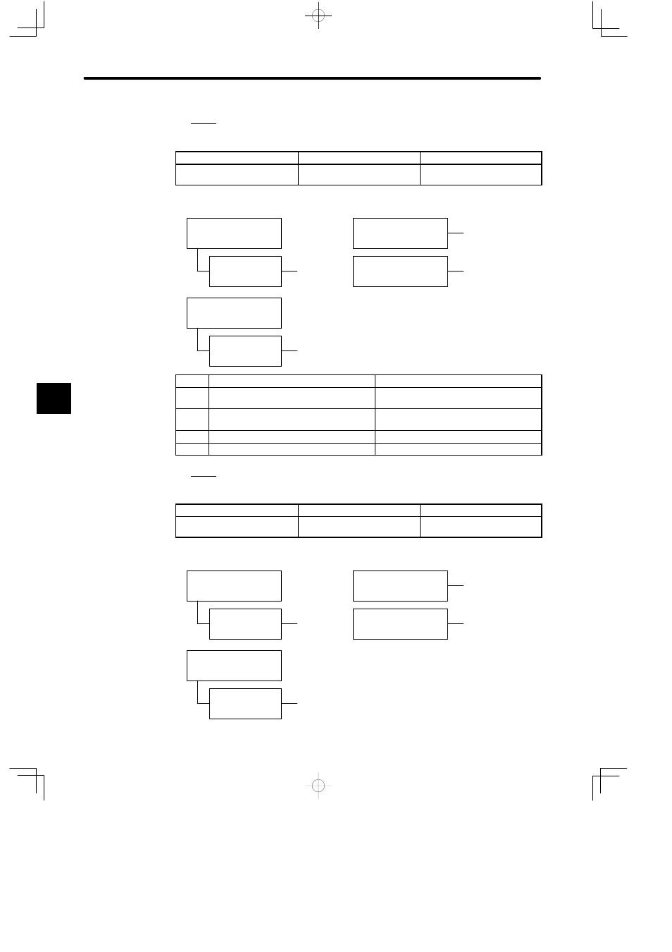
11.A.C3
Display and Outputs
Digital Operator Display
Alarm Name
Alarm Output
A.C3
Encoder phase-A, -B
discontinuity
Output transistor is OFF
(alarm state)
Status when Alarm Occurred
D
At power ON
Parameter
Cn-01 bit 0 = 0
When servo ON (/S-ON)
signal turned ON
A
, B, C, D
During Servomotor
operation
A, B, C, D
A
, B, C
1 to 3 seconds after
power ON
Parameter
Cn-01 bit 0 = 1
Cause
Remedy
A
Encoder wiring incorrect or poor
connection.
Check wiring and connectors at encoder.
B
Noise in encoder wiring.
Separate encoder wiring from main wiring
circuits.
C
Encoder defective.
Replace Servomotor.
D
Circuit board (1PWB) defective.
Replace Servopack.
12.A.C4
Display and Outputs
Digital Operator Display
Alarm Name
Alarm Output
A.C4
Encoder phase-C discontinuity Output transistor is OFF
(alarm state)
Status when Alarm Occurred
C
At power ON
Parameter
Cn-01 bit 0 = 0
When servo ON (/S-ON)
signal turned ON
A
, B, C, D
During Servomotor
operation
A, B, C, D
A
, B, C, D
1 to 3 seconds after pow-
er ON
Parameter
Cn-01 bit 0 = 1
5