Yaskawa Sigma Mini User Manual
Page 75
2.2Setting Parameters According to Host Controller
— 2-31 —
Contact Input Speed Control Operation
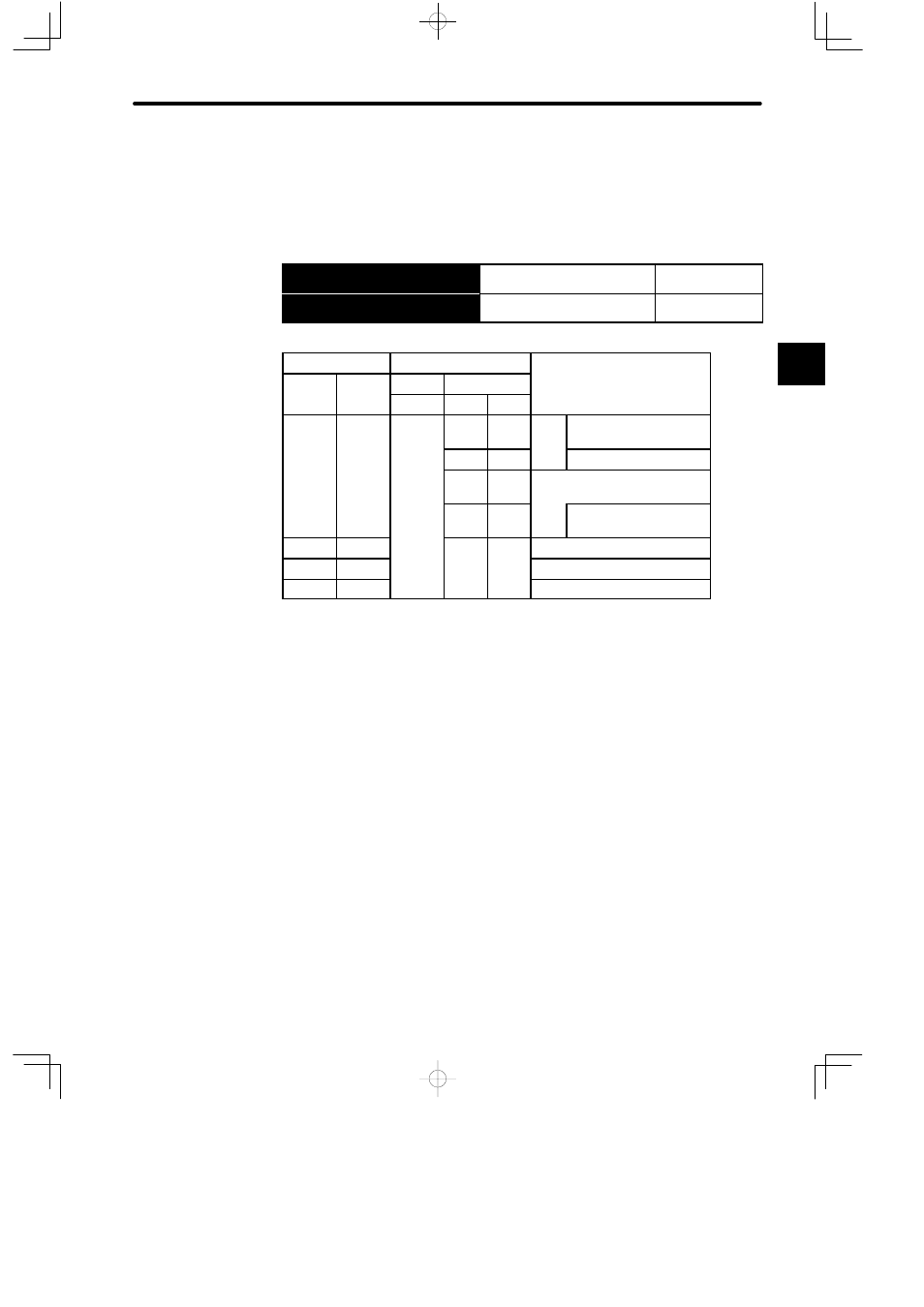
Contact input speed control performs the following operation.
The following input signals are used to start and stop the motor.
→ Input IN1 CN1-1
Speed Selection 1
For Speed/Torque
Control
→ Input IN2 CN1-2
Speed Selection 2
For Speed/Torque
Control
Contact Signal
Parameter
IN1
IN2
Cn-02
Cn-01
Selected Speed
IN1
IN2
Bit 2
Bit A
Bit B
p
0
0
Stop
Stopped by internal
speed reference 0
1
0
Stop
Stopped by zero-clamp
0
0
1
0
1
Analog speed reference (V-
REF) input
1
1
1
With zero-clamp func-
tion
0
1
SPEED1 (Cn-1F)
1
1
−−−− −−−− SPEED2 (Cn-20)
1
0
SPEED3 (Cn-21)
Preset values (0 or 1) and input signal status in the portions indicated by horizontal
bars (−) are optional.
Set the rotation directions for Cn-1F, Cn-20, and Cn-21 in bits 3, 4, and 5 of Cn-02
respectively.
Note For the speed/torque control type, control by external reference (voltage refer-
ence) is possible when the contact input speed control function is used by setting
bits A and B of parameter Cn-01.
2