Inspection and maintenance, Internal connection diagram (for position control) – Yaskawa Sigma Mini User Manual
Page 236
Advertising
INSPECTION AND MAINTENANCE
5.2.3 Servopack Connection Diagrams
— 5-16 —
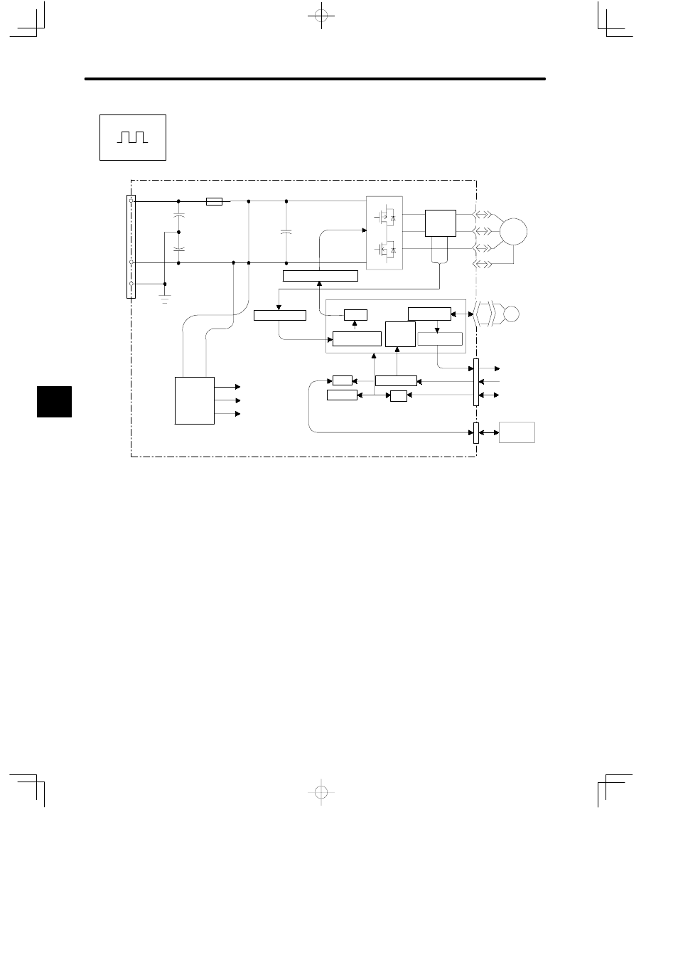
Internal Connection Diagram (for Position Control)
+5V
−5V
PG5V
CN5
CN4
PWM
I/O
CPU
CN1
MOSFET
FG
GND
CN3
24 VDC±10%
Gate Drive Circuit
Current Detection
Control
Power
Supply
PG Signal
Processing
Reference
Counter
Digital Current
Amplifier
PG Signal Divider
For I/O Signals
For Digital
Operator
For PG Pulses
For References
(Pulses)
Photocoupler
EEPROM
Current
Detector
CN2
FG
U
W
V
Servomotor
Encoder
M
PG
5
Positions
Advertising