Yaskawa Sigma Mini User Manual
Page 258
SERVO ADJUSTMENT
A.3.2 Manual Adjustment
— A-12 —
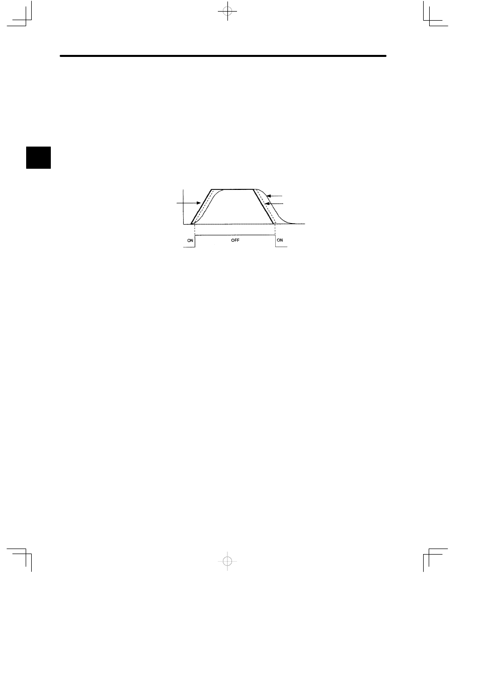
Bias Function
When the lag pulses in the error counter exceeds the positioning complete width
(Cn-1B), the bias amount (Cn-1C) is added to the error counter output (speed reference).
If the lag pulses in the error counter lies within the positioning complete width (Cn-1B), the
bias amount (Cn-1C) is no longer added.
This reduces the number of pulses in the error counter and shortens the positioning time.
The motor speed becomes unstable if the bias amount is too large.
Observe the response during adjustment as the optimum value depends on the load,
gain, and positioning complete width.
Set Cn-0C to zero (0) when the bias is not used.
Speed
Speed
Reference
Positioning Complete
(/COIN) Signal
Motor Speed with No Bias
Motor Speed with Bias
Time
The adjustment procedures described above are common for all Yaskawa digital AC Servo-
packs. However, not all functions are available on each Servopack. Consult the technical
specifications of your Servopack for details.
The adjustment procedures are also identical for conventional analog servos. However, in
this case, the adjustments are made using potentiometers instead of the parameters.
A