2 main circuit wiring and power on sequence – Yaskawa Sigma Mini User Manual
Page 27
BASIC OPERATION
1.3.2 Main Circuit Wiring and Power ON Sequence
— 1-14 —
1.3.2 Main Circuit Wiring and Power ON Sequence
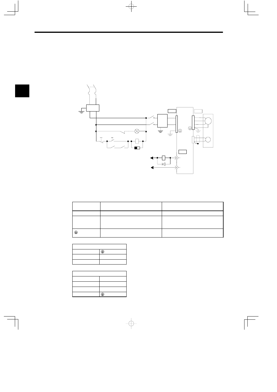
This section shows a typical example of wiring the main circuit for Σ-Series Servo, and de-
scribes the main circuit terminal functions and power ON sequence.
Typical Wiring Example
SG-COM
Single-phase 100 VAC
(50/60 Hz)
Servopack
Servomotor
24 VDC
Power
supply
CN3
CN4
CN1
GND
ALM
PG
M
7
3
+24 V
0
24
V
Ry
SUP
MC
MC
Ry
ON
OFF
Ry
MC
FIL
QF
QF:
Circuit breaker
FIL:
Noise filter
MC:
Contactor
Ry:
Relay
PL:
Patrol light
SUP:
Surge suppressor
D:
Flywheel diode
Overview and Functions of Main Circuit Terminals
The following tables show the name and description of each main circuit terminal function.
Terminal
Symbol
Name
Description
CN3
Main input terminal
24 VDC ±10%
CN4
Motor connection terminal
Connect U to the red motor terminal,
V to the white motor terminal, and W
to the blue motor terminal.
Ground terminal
Connect to a ground and to the motor
(green).
CN3
1
2
GND
3
24 VDC
CN4
1
Phase U
2
Phase V
3
Phase W
4
1