Connectors, functions, controls and displays, Front – KLING & FREITAG K&F CD 44 Digital System controller User Manual
Page 12
User's manual
K&F CD 44 Digital System Controller
KLING & FREITAG GMBH © 2014
Version 11.6
Page 12 of 77
6.
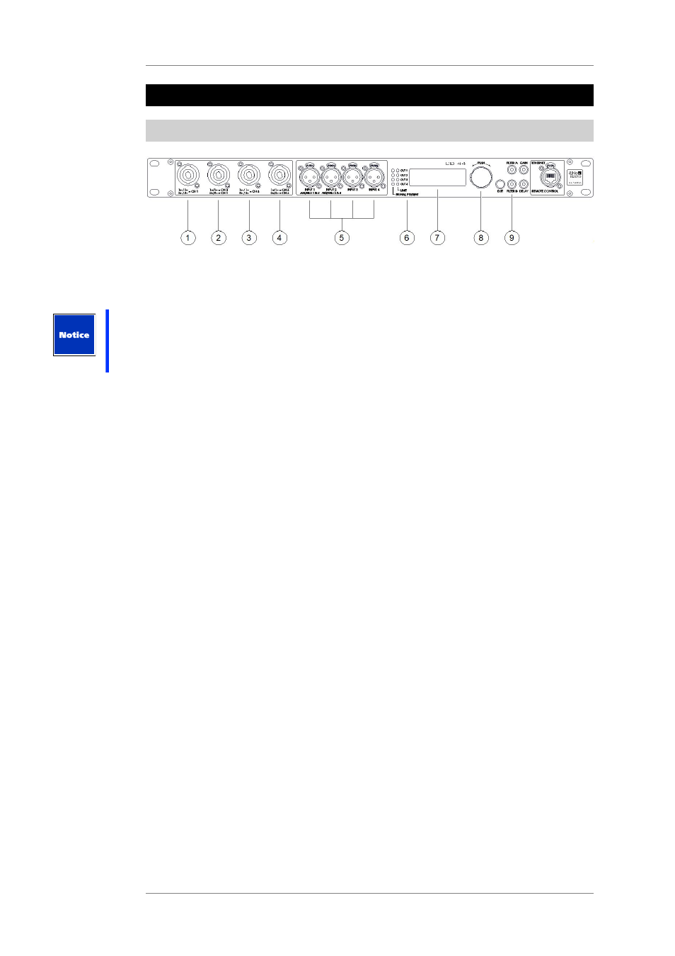
Connectors, Functions, Controls and Displays
6.1
Front
1 - 4: Speaker connectors (4x)
4-pin Speakon connectors. All Kling & Freitag speakers that are, by default, connected with
1+ / 1- can be plugged into these connectors.
Caution: The connectors with the position numbers 1 and 3 are connected differently than
the connectors with the position numbers 2 and 4.
In some cases, mixing up the speaker channels can lead to destruction of the speakers
(example: treble on bass output).
1.
This output connector supplies the signal for the speaker channel 1. In this connector,
the pin 1+ is bridged with 2+, the pin 1- with 2-. The signal for channel 1 is, therefore,
applied to 1+ / 1- as well as 2+ / 2-.
2.
This output connector transmits signals for 2 speaker channels:
The signal for the speaker channel 2 is applied to 1+ / 1-.
The signal for the speaker channel 1 is applied to 2+ / 2-.
3.
This output connector supplies the signal for the speaker channel 3. On this connector,
the pin 1+ is bridged with 2+ and pin 1- with 2-. The signal for channel 3 is, therefore,
applied to 1+ / 1- as well as 2+ / 2-.
4.
This output connector supplies signals for 2 speaker channels:
The signal for the speaker channel 4 is applied to 1+ / 1-.
The signal for the speaker channel 3 is applied to 2+ / 2-.
1 + 3: If you want to use the CD 44 to operate subwoofers whose 2 chassis are controlled
by separate supply lines (ACCESS B5 and ACCESS B10), then you should use these
connectors for these subwoofers in order to control the speakers via a common channel
without an adapter (CH1 or CH3). Fore more information see configuration example on
page 46.
2 + 4: You should use these connectors for ACCESS tops T5 and T9, Sequenza 10 N / W or
NOMOS XLC, because these systems must be controlled using 2 channels.
In order to implement a one-cable system (control of a top and subwoofer via a 4-core
supply cable), you must use these connectors, because the top and subwoofer must be
controlled using 2 different channels.
5.
Signal input connectors: INPUT 1 through INPUT 4, 3-pin XLR female connectors.
These signal input connectors can be used both for analogue and for digital signals, in
accordance with the AES / EBU specifications. You must make the selection in the device
about the type of signals it is being supplied with: digital or analogue. Select the type of
signal source before connecting the signals!
Upon delivery, the controller is pre-programmed for the use of analogue input signals.
These inputs correspond to the connectors on the rear panel and are wired in parallel
with them.