Input and output delays (delay button), Infowindow: display of basic settings, 4 input and output delays (delay button) – KLING & FREITAG K&F CD 44 Digital System controller User Manual
Page 24: 2 infowindow: display of basic settings
User's manual
K&F CD 44 Digital System Controller
KLING & FREITAG GMBH © 2014
Version 11.6
Page 24 of 77
According to the room geometry, the actual level balance which needs to be adjusted
may differ from the aforementioned reference values. It is, therefore, always necessary
for a sound technician to carry through fine adjustments of the output gains when the
system is set up.
7.1.4
Input and Output Delays (Delay Button)
After pushing the DELAY button, the first settings you access are for the input delays. Pushing
the button repeatedly will give you access to the output delays.
The units for the delays can be converted from milliseconds (ms) to metres (m) at <Util »
Units>. The unit ‘Metre’ is based on a sound velocity of 343 m/s at 20°C.
If one of these delay values is not zero, the red LED on the DELAY button lights up.
1.
Use the Input Delays to create delay lines.
Delay lines are speakers which are set up behind one another. The delay times of the
speakers’ sound propagation is compensated using delays.
The purpose of delay lines is to ensure that the sound from the speakers near the stage
reaches the listeners in the back of the audience simultaneously (preferably) with the
sound from the speakers in the rear audience area.
You can separately adjust the delays of up to four input channels, with every channel
having a total available delay of 200 ms or 68.6 m. Because a delay of 0.02 ms is already
set up in the LS-Block ACCESS High, the available delay time when using this LS-Block is
reduced accordingly by this amount.
2.
Use the Output Delays to compensate differences in delay time of the positioned
speakers, for example from flown tops to standing subwoofers, stage edge speakers to
the main system, etc. You can separately adjust a total of 4 output channels.
Out 1 and Out 2 share 20 ms or 6.86 m delay time.
Out 3 and Out 4 also share 20 ms or 6.86 m delay time.
These values decrease if there is already a delay set in an LS-Block.
If you select a delay of 5 ms or 1.715 m for Out 1, then there are another 15 ms or 5.145
m available for Out 2. The same also applies for Out 3 and Out 4. The value stated next to
‘Avl =’ indicates how much delay time is still available.
7.2
InfoWindow: Display of Basic Settings
A window initially appears, subsequently referred to as InfoWindow 1, approx. 7 seconds
after turning on the device, or when you have not used it for approx. 7 seconds, or after you
have pushed the EXIT button several times. If you are currently in InfoWindow 1, and you
then turn the knob to the right (clockwise), you will access InfoWindow 2. EXIT
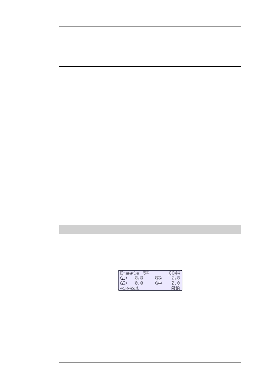
This illustration shows InfoWindow 1 for the loaded setup 'Example 5':
The InfoWindow 1 shows information about the following basic settings:
•
1st line: Name of the loaded setup, here: Example 5. If there is an asterisk next to the
setup name, this means that changes have been made to the setup that have not been
saved yet.
•
2nd and 3rd line: Settings of the Input Gains 1-4 (Depending on routing, 1 to 4
adjustable gains).
•
4th line: type of routing, here: '4in4out' and the selected input sources (ANA =
analogue inputs, AES = digital inputs)