KLING & FREITAG K&F CD 44 Digital System controller User Manual
Page 16
User's manual
K&F CD 44 Digital System Controller
KLING & FREITAG GMBH © 2014
Version 11.6
Page 16 of 77
20
50
100
500
1000
5000
10000
20000
0
3
+6
Frequency in [Hz]
P
o
w
e
r
in
[
d
B
]
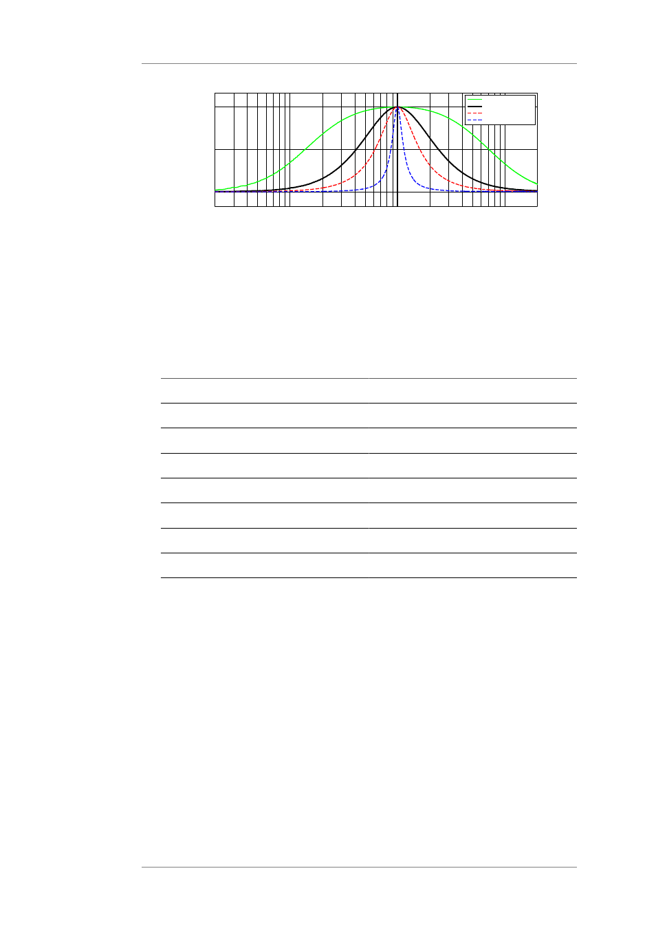
FilterType = 'Bell' (Bell Passband) Gain = +6dB Freq = 1000Hz
Q = 0.2
Q = 0.707
Q = 1.414
Q = 5
The gain determines the maximum or minimum level increase or attenuation of the filter
(in the graph: increase of +6dB.
This 'bell' is logarithmically symmetrical relative to the selected frequency (in the
example: 1000 Hz).
The Q-factor defines the quality of the filter. In doing so, it determines the width of the
frequency range which is to be increased or attenuated. The higher the Q-factor, the
narrower the frequency range. A lower Q-factor thus has a wider range.
"Q" is adjustable in steps of 0.001 from 0.2 to 20.
Typical Q-values and their bandwidth equivalent:
Bandwidth
Q factor
1/3 Oktave (third)
4.318
2/3 Oktave (two thirds)
2.145
1 octave
1.414
1 1/3
1.044
1 2/3
0.819
2
0.666
1/6 octave (whole step)
8.651
2.
HShelv (high shelving filter)
3.
LShelv = Low Shelving Filter
These filters increase (positive gain) or attenuate (negative gain) the frequencies below
or above the selected frequency.
Below = LShelv
Above = HShelv