Rear, 2 rear – KLING & FREITAG K&F CD 44 Digital System controller User Manual
Page 14
User's manual
K&F CD 44 Digital System Controller
KLING & FREITAG GMBH © 2014
Version 11.6
Page 14 of 77
For further information see chapter 'Switchable, Speaker Specific Filters' beginning on
page 21.
12. GAIN Button (Shortcut Button)
Pushing the GAIN button allows you to directly access the input and output gains without
having to navigate through the menu. GAIN
After pushing the GAIN button, the first possible setting is for the signal input (input
gains). If you push it repeatedly, you access the output gains. GAIN
If one of these gain values is not zero, the red LED on the GAIN button lights up. GAIN
For more information, see Capter 'Input and Output Delays' on page 24.
13. REMOTE CONTROL
This RJ45 connector allows for you to connect the CD 44 to a computer or integrate it
into a network in order to execute remote enquiries and remote control or to import
software updates. The connection conforms to Ethernet standards. The IP address can be
changed at <Util » IP Address>.
You can find the latest software versions on www.kling-freitag.de
6.2
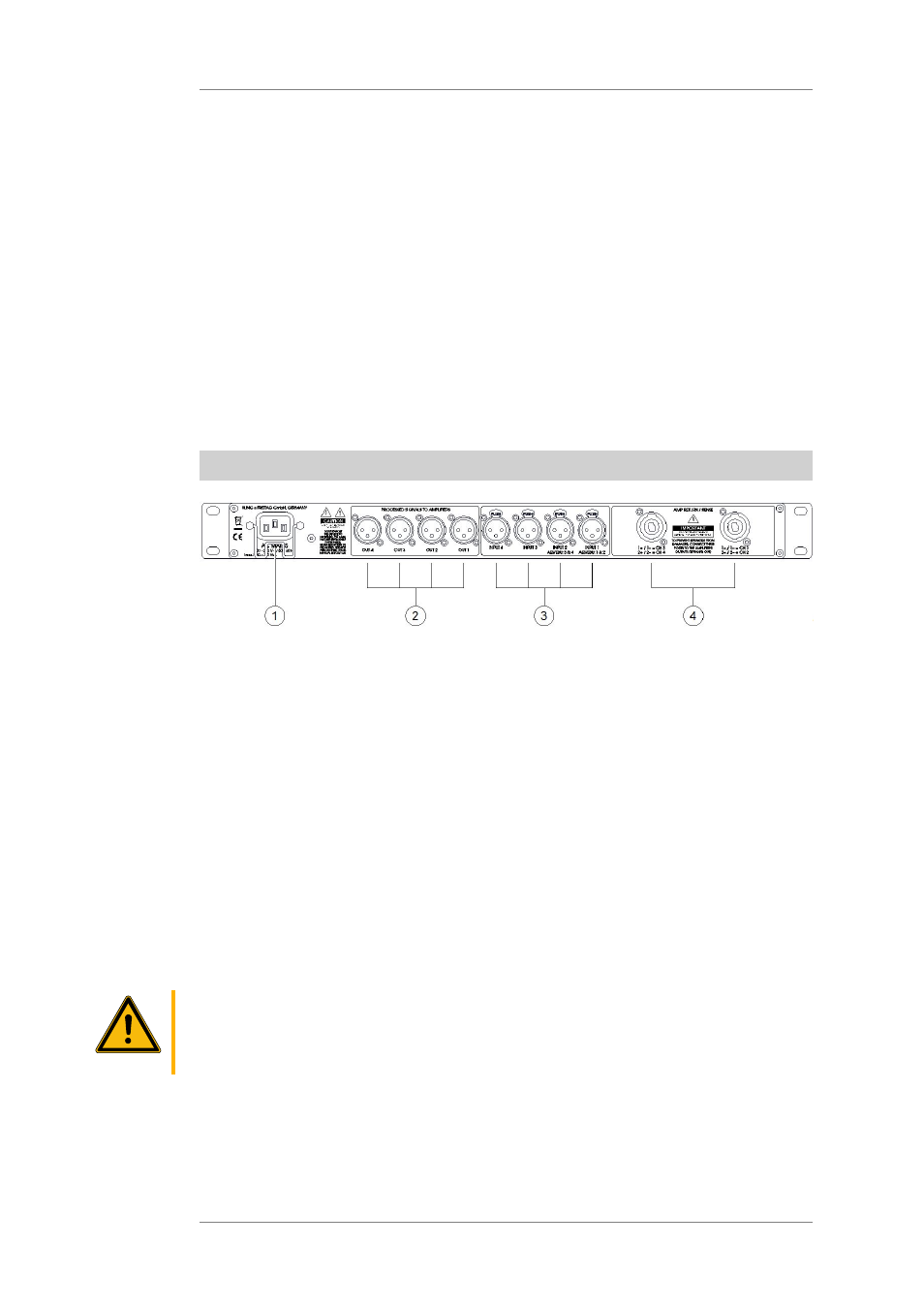
Rear
1.
Power Supply Connector
IEC power socket 100 - 240 V~ / 50 - 60 Hz, I nominal: 150 - 100 mA.
Connect this socket to a mains outlet using the mains cable supplied with the controller.
To avoid an unintentional loosening of the mains cable, the power supply connector is
provided with a safety clamp. Flip the clamp over the connector of the mains cable after
having plugged it into the power supply connector.
Pay attention to the stated mains voltage. Connection to an incorrect mains voltage may
result in irreparable damage!
2.
OUT 1 through OUT 4
3-pin XLR male connector, pin assignment: 1 = ground, 2 = +, 3 = -
These outputs deliver the line signal processed by the controller to the power amplifiers.
Connect these outputs to the inputs of the power amplifiers.
3.
Signal input connectors: INPUT 1 through INPUT 4, 3-pin XLR female connectors.
These connectors correspond to the connectors on the front and are wired in parallel
with them. For a detailed description of the inputs see page 9.
Caution
Do not assign the inputs on the front and rear panel simultaneously. This can lead to
malfunction or damage of other appliances!
4.
AMP RETURN / SENSE
1 + / 1 - = CH 1
1 + / 1 - = CD 3
2 + / 2 - = CH 2
and
2 + / 2 - = CH 4