Bus voltage sensing inputs (optional), Generator voltage sensing inputs, Phase b line current sensing input – Basler Electric DECS-100 User Manual
Page 39: Accessory input, Raise and lower contact inputs, Var/power factor control contact input (optional), Bus voltage sensing inputs (optional) -5, Generator voltage sensing inputs -5, Phase b line current sensing input -5, Accessory input -5
9287500991 Rev M
DECS-100 Installation
4-5
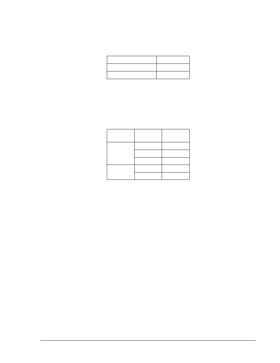
Bus Voltage Sensing Inputs (Optional)
The bus voltage sensing terminals are labeled B1 and B3. These terminals are used only on units that
include the Voltage Matching option. The bus input is not phase sensitive to generator sensing. Table 4-1
lists the terminal assignments for bus voltage sensing.
Table 4-1. Bus Voltage Sensing Terminals
Bus Voltage Phase
Terminal
A
B1
C
B3
Generator Voltage Sensing Inputs
The generator voltage sensing terminals are labeled E1, E2, and E3. The DECS-100 comes equipped for
three-phase sensing as standard. Single-phase sensing is obtained by connecting the C-phase sensing
input to terminals E2 and E3. Table 4-2 lists the terminal assignments for three-phase and single-phase
generator voltage sensing.
Table 4-2. Generator Voltage Sensing Terminals
Sensing
Generator
Phase
Terminal
3-Phase
A
E1
B
E2
C
E3
1-Phase
A
E1
C
E2, E3
Phase B Line Current Sensing Input
Generator line current is stepped down through a user-supplied current transformer (CT). Secondary
current from that transformer is applied to terminals labeled CT1 and CT2.
Accessory Input
The accessory input voltage terminals are labeled A and B and accept a maximum signal of ±3 Vdc.
Positive voltage applied to terminal A with respect to terminal B causes the active mode setpoint to
increase. For every
±1 Vdc change, a ±10% change in the active mode setpoint is achieved.
Raise and Lower Contact Inputs
Remote setpoint adjustment may be accomplished by connecting a single-pole, double-throw (SPDT),
spring return, center-off switch to the terminals labeled 6U, 7, and 6D. To connect this switch, the center
pole, or common terminal, must be connected to terminal 7. The other two terminals are connected to
terminals 6U and 6D.
This remote adjust switch may be mounted up to 150 feet away from the DECS-100 when using twisted,
shielded cable. Only dry, ungrounded switching contacts should be applied to the Raise and Lower
contact inputs.
Var/Power Factor Control Contact Input (Optional)
A customer-supplied enable/disable contact for this function connects to the terminals labeled 52J and
52K.
Only dry, ungrounded switching contacts should be applied to the Var/Power Factor Control contact input.