Metering, operation and alarms, Metering, operation and alarms -15, Operation tab -15 – Basler Electric DECS-100 User Manual
Page 67: Iv va
9287500991 Rev M
DECS-100 BESTCOMS™ Software
5-15
Metering, Operation and Alarms
The Metering, Operation and Alarms screen is viewed by clicking the Metering button or by clicking
Screens on the Menu bar and clicking Metering/Operation. Information displayed on the Metering,
Operation and Alarms screen can be frozen by clicking the Metering button while viewing the screen or by
clicking Metering on the Menu bar and clicking Disable Metering. Metering can be resumed by clicking the
Metering button or by clicking Metering on the Menu bar and clicking Enable Metering. The Metering,
Operation and Alarms screen consists of two tabs: Operation and Alarm/Status.
Operation Tab
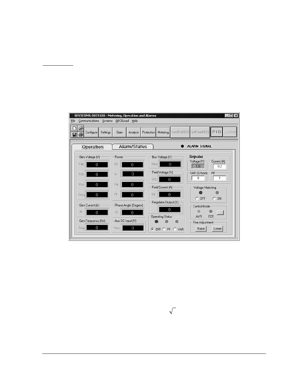
Operation tab metering values, setpoint values, and control functions are illustrated in Figure 5-16.
Gen Voltage (V). These metering values report the status of the V
A-B
, V
C-B
, V
C-A
, and V
AVG
generator
voltages. The reported values are the product of the voltage sensed at terminals E1, E2, and E3 and the
generator PT ratio. All metering values are updated once each second. When single-phase sensing is
used (System Configuration screen, Sensing Voltage) and the DECS-100 sensing voltage terminals (E1,
E2, and E3) are connected as shown in Figures 4-7 or 4-9, all of the generator voltage metering values
will be identical.
Figure 5-16. Metering, Operation, and Alarms Screen, Operation Tab
Gen Current (A). This metering value indicates the level of the B-phase generator current. This value is
the product of the current input to CT1 and CT2 and the CT ratio. Generator current is monitored through
DECS-100 terminals CT1 and CT2.
Gen Frequency (Hz). This metering value indicates the frequency of the monitored generator voltage.
Power - VA. This metering value indicates apparent power and is the calculated product of the metered
generator voltage (V
AVG
), PT ratio (entered at the System Configuration screen), metered generator
current (Ib), CT ratio (entered at the System Configuration screen), and the square root of 3. See
Equation 5-1.
3
×
×
=
B
AVG
I
V
VA
Equation 5-1
Power – W. This metering value indicates real power and is the calculated product of the metered
generator voltage(V
AVG
), PT ratio (entered at the System Configuration screen), metered generator
current (Ib) CT ratio (entered at the System Configuration screen), square root of 3, and the cosine of the
metered phase angle. See Equation 5-2.