Fcr tab -9, Figure 5-10. analysis screen, avr tab -9 – Basler Electric DECS-100 User Manual
Page 61
9287500991 Rev M
DECS-100 BESTCOMS™ Software
5-9
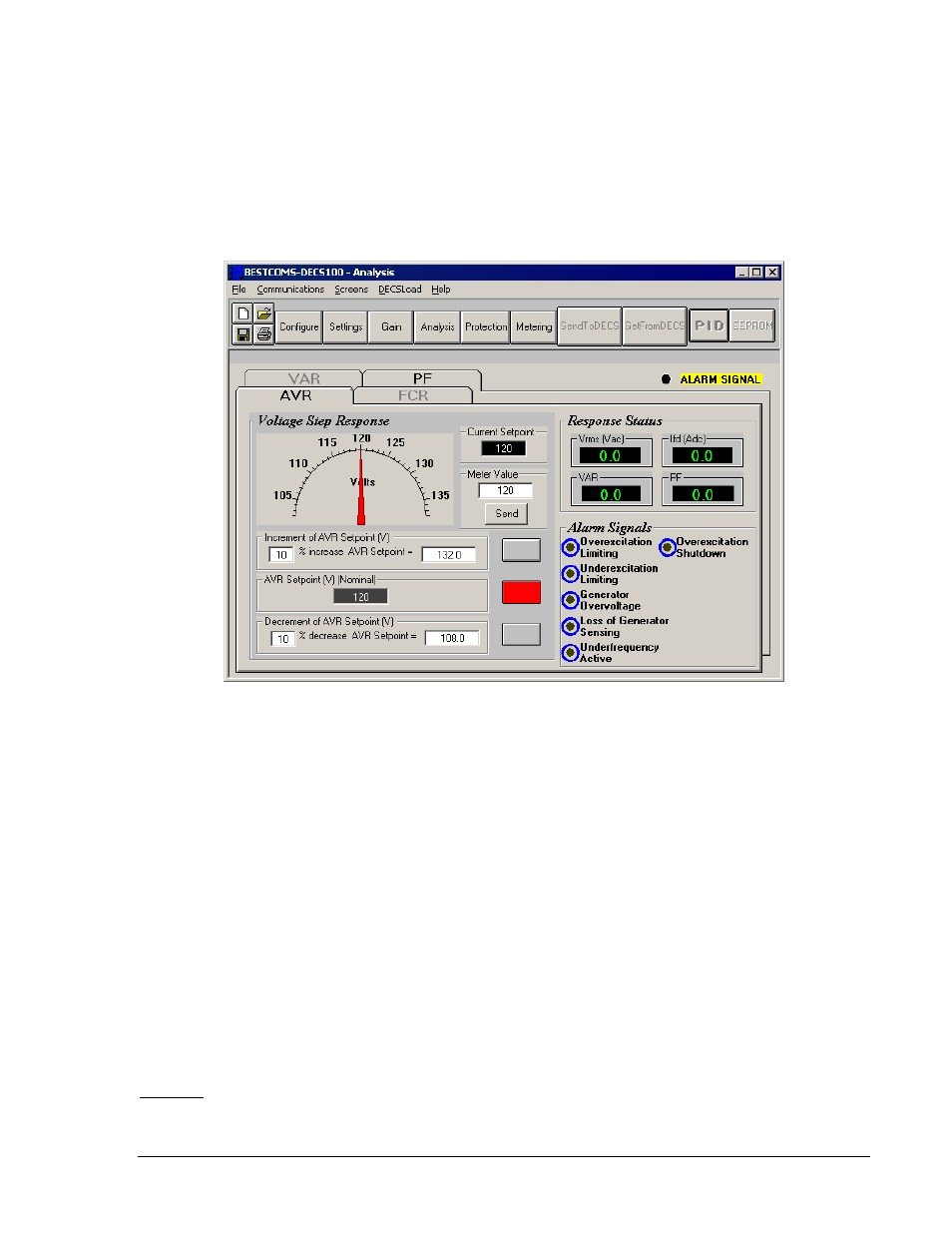
displayed in the AVR Setpoint field is selected by clicking the adjacent button. Clicking this button sends
the AVR Setpoint value to the DECS-100 and changes the color of the button from gray to red.
Voltage Step Response - Increment of AVR Setpoint (V). These two fields indicate the increase that
occurs to the AVR setpoint when the corresponding Increment button is clicked. The "% increase" field is
used to set and indicate the percentage that the AVR setpoint is increased when the Increment button is
clicked. The "AVR Setpoint =" field indicates the value of voltage that corresponds to the "% increase"
field. Any setpoint value within range or higher than the setpoint value can be typed into the "AVR
Setpoint ="field, which updates the "% increase" field. The AVR setpoint changes to this value when the
adjacent button is clicked. When clicked, the Increment button changes from gray to red to indicate that
the AVR setpoint has increased to the value in the "AVR Setpoint =" field.
Figure 5-10. Analysis Screen, AVR Tab
Voltage Step Response - Decrement of AVR Setpoint (V). These two fields indicate the change that will
occur to the AVR setpoint when the corresponding Decrement button is clicked. The "% decrease" field is
used to set and indicate the percentage (0 to 10%) that the AVR setpoint is decreased when the
Decrement button is clicked. The "AVR Setpoint =" field indicates the value of voltage that corresponds to
the "% decrease" field. Any setpoint value within range or lower than the setpoint value can be typed into
the "AVR Setpoint =" field, which updates the "% decrease" field. The AVR setpoint changes to this value
when the adjacent button is clicked. When clicked, the Decrement button changes from gray to red to
indicate that the AVR setpoint has decreased to the value in the "AVR Setpoint =" field.
Voltage Step Response - Meter Value. This field and the dial pointer indicate the value of the selected
AVR setpoint. When the AVR setpoint is changed by clicking the increment, decrement, or setpoint
button, the meter value field and dial pointer indicate the new setpoint value. A new AVR setpoint can be
typed directly into the Meter Value field or selected by dragging the dial pointer to the desired value. The
new value is sent to the DECS-100 by clicking the Send button.
Voltage Step Response - Current Setpoint. The active DECS-100 setpoint (adjusted by using any of the
previously mentioned methods) is displayed in this field. To return the AVR setpoint to the nominal
setting, the button adjacent to the "AVR Setpoint (V) (Nominal)" field should be clicked. If the AVR tab is
left to view other tabs or screens without returning the AVR setpoint to nominal, an AVR dialog box
appears. Clicking the Yes button returns the AVR setpoint to nominal. Clicking No maintains the AVR
setpoint at the current value.
FCR Tab
Figure 5-11 illustrates the settings, sensing values, and alarm signal indicators of the FCR tab. The
settings of the FCR tab make it possible to increment and decrement the FCR setpoint of the DECS-100.