Operation – Beisler 1265-4 User Manual
Page 26
Operating Instructions Automatic Single-Head Serging Machine 1265-4
Beisler GmbH
B-16
B.3
Operation
B.3.1 Preparing the machine
Prior to a production start, check the supply connections, connect the ma-
chine to the compressed air system and to the power supply system, and
prepare the sewing head.
1. Connect the machine to the power supply system.
WARNING - Electric shock!
Contact with current-carrying components may cause a le-
thal electric shock. Check plug and cable before connecting
machine to power supply system.
Do not use damaged plugs, sockets or cables to con-
nect the machine to the power supply system!
The machine is operated with a supply voltage of 230 V
± 10 % at 50/60 Hz. The power supply cable must have
a minimal cross section of 1,5 mm.
Before connecting the machine to the power supply sy-
stem, check to see if the ratings of the power supply
system in the operating room correspond with the ra-
tings on the nameplate at the rear of the machine.
If the ratings for voltage (V) and maximum current (A)
do not match, the machine must not be connected.
Insert the grounding plug into a properly grounded and
fused power socket.
Make sure that the power supply cable is not subjected
to tensile or pressure forces.
2. Switch the machine on by moving the main switch to position I. After
the machine has been switched on, its control program is powered up.
The display shows the most recently selected sewing program.
3. Switch the heating module on. Wait until the red indicator goes off to
indicate that the lower stamp has reached its operating
temperature.
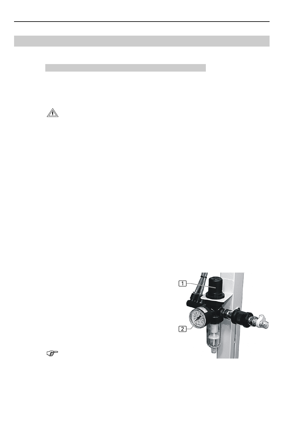
4. Fig. 15: Connect the machine to the compressed air
supply system by installing the compressed air hose
connector to the outlet of the compressed air supply sy-
stem in the operating room. A pressure reducer 1 re-
duces the compressed air to the operating pressure of
6 bar. Check the manometer 2 to see if the correct
operating pressure has been set. The pressure reducer
is located at the machine frame.
5. Insert needle, pass top thread through needle and install
bottom thread spool to sewing head (see operating in-
structions of sewing head manufacturer or supplier).
NOTE - Passing thread through needle
The program control supports the passing of the thread th-
rough the needle on both machines.
Fig. 15