Electrical diagram for external safety switches – Hypertherm HyIntensity Fiber Laser Rev.3 User Manual
Page 63
InstallatIon
HyIntensity Fiber Laser
Instruction Manual – 807090 Revision 3
2-15
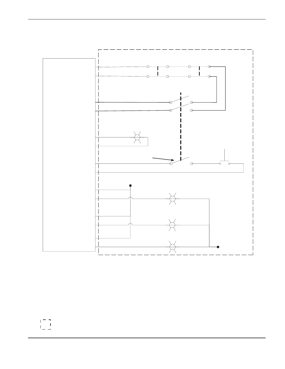
Electrical diagram for external safety switches
Recommended components:
E-Stop switch – Rockwell Automation part numbers 800FP-LMT44, 800F-PN3R, and (2) 800F-X01
Start/Reset switch – Rockwell Automation part numbers 800FP-LF3, 800F-PN3G, and 800F-X01
Key switch – Rockwell Automation part numbers 800FP-KM21 and 800F-X10
Stack light – Rockwell Automation part numbers 855D-P00SC20B24Y3Y5L4
= Customer supplied components
A-1
A-2
External Door
Interlock
External E-Stop
Key Switch (optional contacts)
Key Switch
Start/Reset
Momentary Switch
Start/Reset
Switch Indicator
+24 VDC
Red Stack Light
Yellow Stack Light
C-2
C-1
A-3
C-3
A-4
C-4
A-7
C-7
A-6
C-6
A-5
C-5
Green Stack Light
LPC2
(supplied by user and machine
mounted)