Modbus digital control, Wiring, Modbus communication requirements – Nortec NH-EL Series User Manual
Page 38
35 | Installation
Modbus Digital Control
The NH-EL humidifier comes standard with a Modbus communication interface. The Modbus
interface can be configured to control the humidifiers output or can be used to monitor its
operation. See Nortec document 2560599 – Using Modbus with Nortec Humidifiers for a listing
of Modbus parameters that are available with the NH-EL.
Wiring
Table 8 provides information on Modbus wiring requirements. The NH-EL uses a three pole
terminal, the Integrated Controller PCB, to provide Modbus communications. Connections can
be made directly to this terminal.
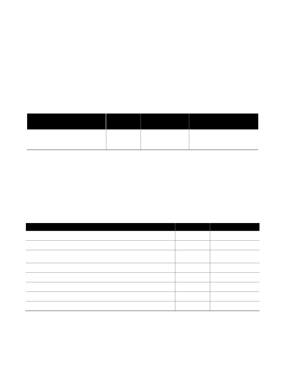
Table 8: Modbus Wiring Requirements
BMS
Protocol
Signal Type
Recommended
Cable
Max. Recommended Distance
from Nortec Module to BMS
Modbus
EIA-485,
2-wire
18-24 AWG
Shielded, Twisted
Pair, 120 Ω*
Should not exceed 2200 ft
* Connect humidifiers in daisy chain to the Modbus RTU. Ground shield at one end only (BMS or humidifier)
Modbus Communication Requirements
Table 9: Modbus Communication Parameters lists the requirements for Modbus communication
with the NH-EL and the range of adjustable parameters. Adjustable parameters are set using
the LCD touchscreen of the NH-EL in the Factory Menu Level which is not accessible to users. If
the parameters must be changed from default, refer to the Nortec document 2560599 – Using
Modbus with Nortec Humidifiers.
Table 9: Modbus Communication Parameters
Item
Default
Adjustment Range
Signal Type*
EIA-485
-
Transmission Mode*
RTU
-
Baud Rate
9600
9600, 19200,
38400, 115200
Data Bits*
8
-
Stop Bits*
1
-
Parity
Even
Odd, Even, None
Address
1
1-247
Timeout
300 s
0-300 s
* Parameters not adjustable