Nh-el wiring diagram (cylinder a), Ss s, Nh-el series humidifier (cylinder a) – Nortec NH-EL Series User Manual
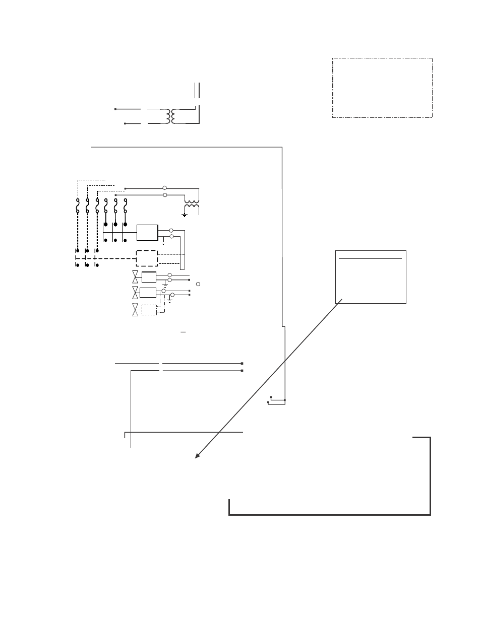
Page 84: L1 l2 l3, Circuit for cylinder a, Built on blower pack primary power, External internal, Optional, Figure 52: wiring diagram for nh-el (cylinder a), Cylinder 2,3, and 6 electrode
L1
L2
L3
COM
Fault Remote PCB
NO
NC
Steam
Unit ON
Error
Service
COM
NO
NC
COM
NO
COM
NO
Cylinder
2,3, and 6 electrode
High
Water
Plug
1
2
3 4
5 6 7
8
9
Blower Pack
Air Proving
+
N.O.
Security
Loop
(-) Signals
(+) Control Signal
(+) Limit Signal
+ 10 Vdc
GND
Circuit for Cylinder A
Door Interlock
Switch
ON/OFF
Switch
Built On
Blower Pack
Primary Power
Cyl. A
Cyl. B
Aux. Drain
Switch
A
B
C
D
E
3.0 A (005-100)
4.0 A (150-200)
NH-EL SERIES HUMIDIFIER (Cylinder A)
WIRING DIAGRAM
DIAGRAM No. 2569828 REV. E Date: July 4, 2014.
.. .
CONTROL
BLOWER
POWER SUPPL
Y
CURRENT SENS
LEV. SENSOR
LIMIT
10V
F1
V+
IN
IN
24V
24Vac
24
24
SL
SL
IN
GND
GND
GND
1
2
3
4
R
R
R
R
R
or
or
R
R
R
R
R
bl
bl
br
br
G
G
G
W
W
W
B
B
B
B
B
B
B
B
{
Cylinder
B
Diagram
(2569829)
U U
U
U
J15
J1
J2
J3
J6
J10
J12
J14
J19
J21
J23
J16
Master/Slave
Port
For cylinder A identification
DIP switch 1 and 2 must be
in the OFF position
Contactor
Contactor
Optional Fuses
Fill V
Fill V
Drain V
PRI
SEC
F
S
or
or
R
R
G
W
W
B
B
Optional for
drain water
cooling
CONTACTOR
INLET
DRAIN
External
Internal
S
S
S S
120V
PRI
Transformer
(if required)
Fuse 1 Amp
(if Required)
Fuse 1.5 A
(if required)
OPTIONAL
NH-EL Wiring Diagram (Cylinder A)
Figure 52: Wiring Diagram for NH-EL (Cylinder A)