Analog input confi guration screen, Gpc-xp controller technical guide, Confi guring analog inputs – Orion System GPC-XP Controller User Manual
Page 13
GPC-XP Controller Technical Guide
Section 4: Confi guring Analog Inputs
13
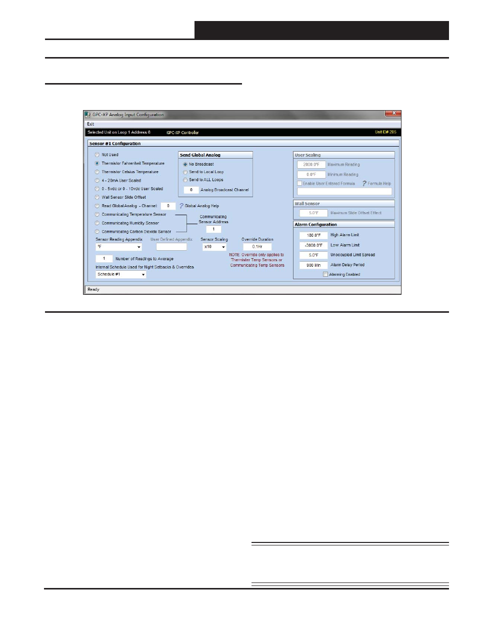
Analog Input Confi guration Screen
Confi guring Analog Inputs
Left-click in the data entry fi eld in the Analog Inputs Window to
open the Analog Input Confi guration Window (Figure 11 below).
The following confi gurations are available for each Analog Input:
● Not Used
● Thermistor Fahrenheit Temperature: 10K Ohm Type III
Scaled for Fahrenheit. Set jumper to the appropriate setting
(Figure 2, page 6.)
● Thermistor Celsius Temperature: 10K Ohm Type III
Scaled for Celsius. Set jumper to the appropriate setting
(Figure 2, page 6.)
● 4 - 20mA User Scaled: 4-20mA User-Scaled Sensor
● 0 - 5vdc or 0-10 vdc User Scaled: Select this option
if using a 0-5vdc or 10vdc scaled sensor. Set jumper
associated with this input to the appropriate 0-5v or 0-10v
setting (Figure 2, page 6.)
● Wall Sensor Slide Offset: If using a WattMaster
thermistor space sensor with the slide adjust, this would be
the input confi guration for the AUX connection from that
sensor.
● Read Global Analog – Channel: See Figure 110, page
48 for an explanation of Analog Globals. Left or right click
on the Question mark beside Global Analog Help to access
information about the Global Broadcasts and to view pre-
defi ned channels.
● Communicating Temperature Sensor: If using a
WattMaster Communicating Temperature Sensor with a
modular cable, confi gure this input to read the appropriate
Communicating Sensor Address. Enter an address from
1-8 in the < Communicating Sensor Address> fi eld and
press
<ENTER>
. If using a combination Temperature and
Humidity Communicating Sensor, confi gure one input to
read the temperature and another input to read the humidity,
both using the same Communicating Sensor address.*
● Communicating Humidity Sensor: If using a
combination Temperature and Humidity Communicating
Sensor with a modular cable, confi gure one input to read
the temperature and another input to read the humidity,
both using the same Communicating Sensor address. Enter
an address from 1-8 in the <Communicating Sensor
Address>
fi eld and press
<ENTER>
.*
● Communicating Carbon Dioxide Sensor: If using a
WattMaster Communicating CO
2
Sensor with a modular
cable, confi gure this input to read the appropriate Comm-
unicating Sensor Address. Enter an address from 1-8 in
the <Communicating Sensor Address> fi eld and press
<ENTER>
.*
● Communicating Combination Outdoor Air Temperature
and Humidity Sensor:
If using a WattMaster Comm-
unicating Combination Outdoor Air Temperature and
Humidity Sensor, confi gure one input to read the temperature
and another input to read the humidity. For each input, enter
<25>
as the Communicating Sensor Address. Only one of
these sensors can be used on a GPC-XP.
*NOTE: See the appropriate E-BUS Digital Room Sensor or
E-BUS Digital CO
2
Sensor Technical Guides for
information on how to address the communicating
sensors.
Figure 11: Analog Input Confi guration Window