Control type – Orion System GPC-XP Controller User Manual
Page 30
Section 7: Confi guring Analog Outputs
GPC-XP Controller Technical Guide
30
Control Type
Floating Point Control
Floating Point Control works best on slow changing applications
where the amount of time it would take to drive full on or full off
is not as critical. For faster response, the PID Control method is
recommended.
With Direct Acting Floating Point Control, as the selected Control
Source rises above Setpoint, the Analog Output voltage signal in-
creases to try to maintain the Setpoint. As the Control Source falls
below Setpoint, the Analog Output voltage signal decreases.
With Reverse Acting Floating Point Control, as the selected Control
Source rises above Setpoint, the Analog Output voltage signal de-
creases to try to maintain the Setpoint. As the Control Source falls
below Setpoint, the Analog Output voltage signal increases.
A Deadband above and below the Setpoint can be confi gured in
which no control signal change is made.
With Floating Point Control, you can confi gure a Calculation Interval
and a Proportional Control Window. See Figure 55 below.
Calculation Interval
- Determines how often the control signal
calculation is made to try to reach setpoint. Setting this too fast can
cause over-shooting.
Proportional Control Window - Determines how large of a sig-
nal change will occur at each Calculation Interval. The larger the
Proportional Window, the smaller the signal change will be at each
Calculation Interval.
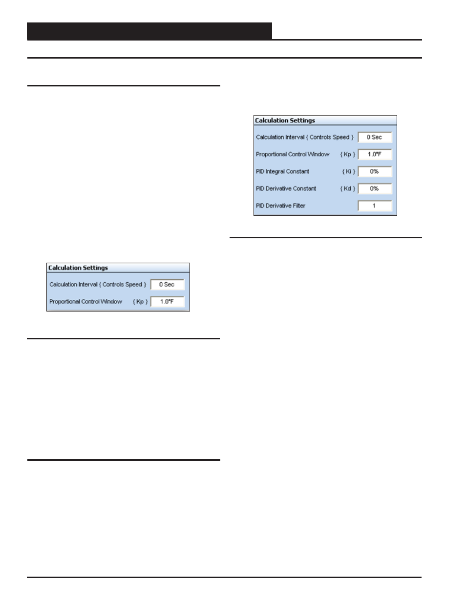
PID Control
PID Control allows Proportional, Integral, and Derivative Rate of
Change Control. With this option, you can confi gure the Proportional
Control Window, an Integral Constant, and a Derivative Constant
as well as the Calculation Interval and PID Derivative Filter. See
Figure 56.
With Direct Acting PID Control, as the selected Control Source rises
above Setpoint, the Analog Output voltage signal increases to try to
maintain the Setpoint. As the Control Source falls below Setpoint,
the Analog Output voltage signal decreases.
Figure 55: Calculation Settings for Floating Point
Control
Figure 56: Calculation Settings for PID Control
Calculation Interval
- Determines how often the control signal
calculation is made to try to reach setpoint. Setting this too fast can
cause over-shooting.
Proportional Control Window
- Determines how large of a sig-
nal change will occur at each Calculation Interval. The larger the
Proportional Window, the smaller the signal change will be at each
Calculation Interval.
Integral Constant - Accelerates the movement of the process
towards setpoint and eliminates the residual steady-state error that
occurs with a pure proportional controller. However, since the inte-
gral term responds to accumulated errors from the past, it can cause
the present value to overshoot the setpoint value. We recommend to
start with a small Ki and increase it until a small overshoot occurs
and then dial it back.
Derivative Constant - The derivative term slows the rate of change
of the controller output. Derivative control is used to reduce the
magnitude of the overshoot produced by the integral component
and improve the combined controller-process stability. However,
the derivative term slows the transient response of the controller.
Also, differentiation of a signal amplifi es noise and thus this term in
the controller is highly sensitive to noise in the error term, and can
cause a process to become unstable if the noise and the derivative
gain are suffi ciently large. We recommend to start with a small Kd
and increase it until overshoot is reduced to desired point.
PID Derivative Filter - The controller will average this number of
input changes in order to smooth out a fast changing value.
If the Derivative Constant (Kd) is set to “0,” then control will be
the Proportional/Integral (PI). If both the Derivative Constant (Kd)
and the Integral Constant (Ki) are set to “0,” then the control will
only be Proportional.
With Reverse Acting PID Control, as the selected Control Source
rises above Setpoint, the Analog Output voltage signal decreases
to try to maintain the Setpoint. As the Control Source falls below
Setpoint, the Analog Output voltage signal increases.