Timing & alarming & relay output type – Orion System GPC-XP Controller User Manual
Page 27
GPC-XP Controller Technical Guide
Section 6: Confi guring Relays
27
Timing & Alarming & Relay Output Type
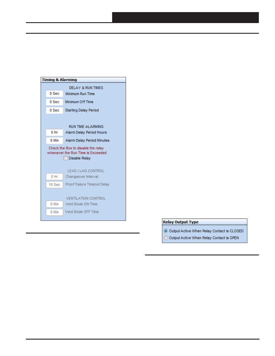
Timing & Alarming
The Timing & Alarming Window (Figure 49 below) is located on the
right of the Relay Confi guration Screen (Figure 34, page 21). The
corresponding fi elds that you need to fi ll out will become available
based on your previous selections.
Figure 49: Timing & Alarming Window
Delay & Run Times
Once activated, the Relay can be forced to remain “On” for the
“ Minimum Run Time.” Once de-activated, the Relay can be forced
to remain “Off” for the “ Minimum Off Time.” The “ Starting Delay
Period” is the period of time before the Relay is called to activate
and the time it is actually energized.
Run Time Alarming
If the selected relay output is controlling a device that needs peri-
odic maintenance, you can enter a “ Run Time Alarm Delay Period”
that once exceeded generates an alarm. If you need to protect the
equipment, you can select the Disable Relay box, and the relay will
de-activate once this run time has been exceeded. To reset the Run
Time Alarm, you must cycle power or uncheck the Disable Relay
box and then re-check the box.
Lead/Lag Control
If you have confi gured this relay for “Lead Relay for Lead/Lag
Control,” you will also need to set the “Changeover Interval” and
the “Proof Failure Timeout Delay.”
The Changeover Interval is used to toggle the Lag output into the
Lead output once the runtime hours of the Lead output exceed this
amount of time on the Lag output.
The Proof Failure Time Out Delay is the amount of time given for the
“Proof Source” input to become active once the Lead or Lag output
is energized. If this proof is not made within the specifi ed amount
of time, the controller switches to the Lag output in an attempt to
get the controller running and then sets an alarm to fl ag the user that
a failure has occurred. See Lead /Lag information on pages 22-24
for more detail.
Ventilation Control
If you confi gured the relay for “Ventilation Control,” you can set
the “ Vent Mode ON Time” and the “ Vent Mode OFF Time.” This
means that the output is active for the Vent Mode ON Time and then
cycles off for the Vent Mode OFF Time. If the output is not enabled
by a schedule, it will continue to cycle indefi nitely at the On/Off
rate. See additional information on page 23.
Relay Output Type
The Relay Output Type Window (Figure 50 below) is located on
the far bottom right of the Relay Confi guration Screen (Figure 34,
page 21). Normally when the relay is On, the output is active. If
you want to reverse that operation and have the output active when
the relay is Off, select the second option.
Figure 50: Relay Output Type Window