Main control method window, Gpc-xp controller technical guide – Orion System GPC-XP Controller User Manual
Page 23
GPC-XP Controller Technical Guide
Section 6: Confi guring Relays
23
Main Control Method Window
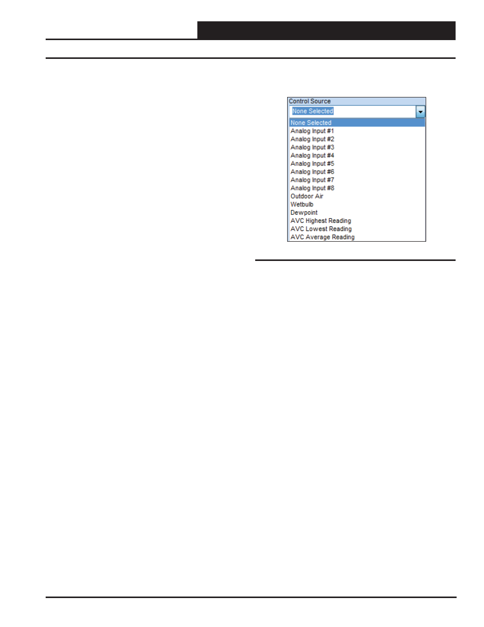
Figure 37: Control Source Field
● Follow Schedule – If this option is selected, you must
then go to the Controlling Schedule fi eld (Figure 43,
page 25)—and select the desired Schedule. This relay
will be energized whenever the selected Schedule is in the
Occupied Mode. See the Setting Schedule Section on page
35 on how to set up Schedules. (This option is not available
with Logical AND/OR operations. See page 26.)
● Ventilation Control – If this option is selected, you must
then go to “Ventilation Control” at the bottom right of the
Relay Confi guration Screen (Figure 34, page 21). There
you can confi gure a “Vent Mode ON Time” and a “Vent
Mode OFF Time.” This relay will then energize for the
duration of the confi gured “Vent Mode ON Time” and
then will de-energize for the duration of the confi gured
“Vent Mode OFF Time.” You have the option of selecting
a Controlling Schedule for this function to follow. If no
Schedule is confi gured, this relay will cycle continuously
for the Vent Mode On/Vent Mode Off operation. If a
Schedule is confi gured, the Vent Mode On/Off will only
cycle the relay during the scheduled Occupied hours. See
the Ventilation Control description on page 27. (This option
is not available with Logical AND/OR operations. See page
26.)
● Lead Relay for Lead/Lag Control – If this option is
selected, you can also select a Control Source input in
the next fi eld to be used as a Proof of Operation to allow
switching to the Lag Relay upon a failure. This proof can
either be a binary contact activation or an analog input
level. If your Proof is an analog input level, you can then
confi gure either an Increasing or Decreasing Proof Setpoint
(Figure 39, page 24).
If your Proof is a Binary Input, the Proof Failure is initiated
when the selected Binary Input is “Active” (See Confi guring
Binary Inputs on page 18.)
In the Timing and Alarm Section (Figure 34, page 21) at the
right of the Relay Confi guration Screen (Figure 34, page
21), you can confi gure a Lead/Lag Changeover Interval and
a Proof Failure Timeout Delay. For further information, see
the Lead/Lag description on page 27. (This option is not
available with Logical AND/OR operations. See page 26.)
● Lag Relay for Lead/Lag Control – This Lag Relay will
follow the same confi gurations as the Lead Relay.
● Active on ANY Alarm (Not shown in Figure 36)– There
are several Alarm Confi guration options available on the
GPC-XP. If any of these alarm conditions occur, this relay
will energize.
Control Source Field
A Control Source needs to be selected anytime you select one of the
Above/Below Control Methods. A Control Source also needs to be
selected anytime you select “Lead Relay for Lead/Lag Control” and
you need a Proof Source to switch to Lag based on a failure condi-
tion. If you selected any other option as a Control Method, then the
Control Source fi eld is not applicable and will not be available to
make a selection.
When a Control Source is selected, in most cases you will then need
to confi gure Control Source Setpoints – either as Hi/Lo Setpoints or
as Increasing/Decreasing Proof Setpoints. See the Control Source
Setpoints fi eld (Figure 38 & 39, page 24). In some cases, a Binary
Input could be selected as the Control Source (acting as the Proof
Source) for Lead/Lag changeover. For example, a Binary Input
could monitor a Proof of Flow (POF) Switch. When the POF switch
is closed and the Binary Input is Active, the Lead Relay would be
energized. If the POF Switch opens and the Binary Input becomes
Inactive, the controller would switch to the Lag relay. In this case
the Control Source Setpoints would not be used.
The Control Source Options are shown below:
●
Analog Inputs # 1-8
●
Outdoor Air Temp Broadcast
●
OA
Wetbulb
●
OA
Dewpoint
●
AVC Highest Reading
●
AVC Lowest Reading
●
AVC
Average
Reading
●
Binary Inputs #1- 8 (Not shown in Figure 37)
●
Analog Outputs #1- 4 (Not shown in Figure 37)